Branching filter and communication device

a technology of branching filter and communication device, which is applied in the direction of impedence network, electrical apparatus, piezoelectric/electrostrictive/magnetostrictive device, etc., can solve the problems of difficult to make the passband wider, difficult to improve sharpness, and difficult to realize excellent branching filter characteristics, etc., to achieve excellent isolation characteristics

Active Publication Date: 2006-09-12
MURATA MFG CO LTD
View PDF9 Cites 18 Cited by
  • Summary
  • Abstract
  • Description
  • Claims
  • Application Information

AI Technical Summary

Benefits of technology

[0014]In order to overcome the problems described above, preferred embodiments of the present invention provide a branching filter having filters in which the passband is widened and the sharpness on the lower-frequency side and / or the higher-frequency side close to the passband is increased, and having excellent isolation characteristics between the transmission and reception sides, and also provide a communication device including such a novel branching filter.

Problems solved by technology

However, in the branching filter described in Japanese Unexamined Patent Application Publication No. 2001-24476, it was difficult to realize a branching filter having excellent characteristics in which a ladder-type piezoelectric thin-film filter having a wide passband and excellent sharpness outside the passband is provided.
Since the piezoelectric thin-film resonators using a fundamental wave have a large electro-mechanical coupling coefficient, it is difficult to narrow the frequency spacing between the resonance frequency and the antiresonant frequency of the piezoelectric thin-film resonators, and accordingly, it was difficult to improve the sharpness.
However, in this case, since the passband is determined only by the frequency spacing between the resonance frequency and the antiresonant frequency of the parallel resonator and the frequency spacing between the resonance frequency and the antiresonant frequency of the series resonator, it was difficult to make the passband wider.

Method used


Image

  • Branching filter and communication device
  • Branching filter and communication device
  • Branching filter and communication device

Examples


first preferred embodiment

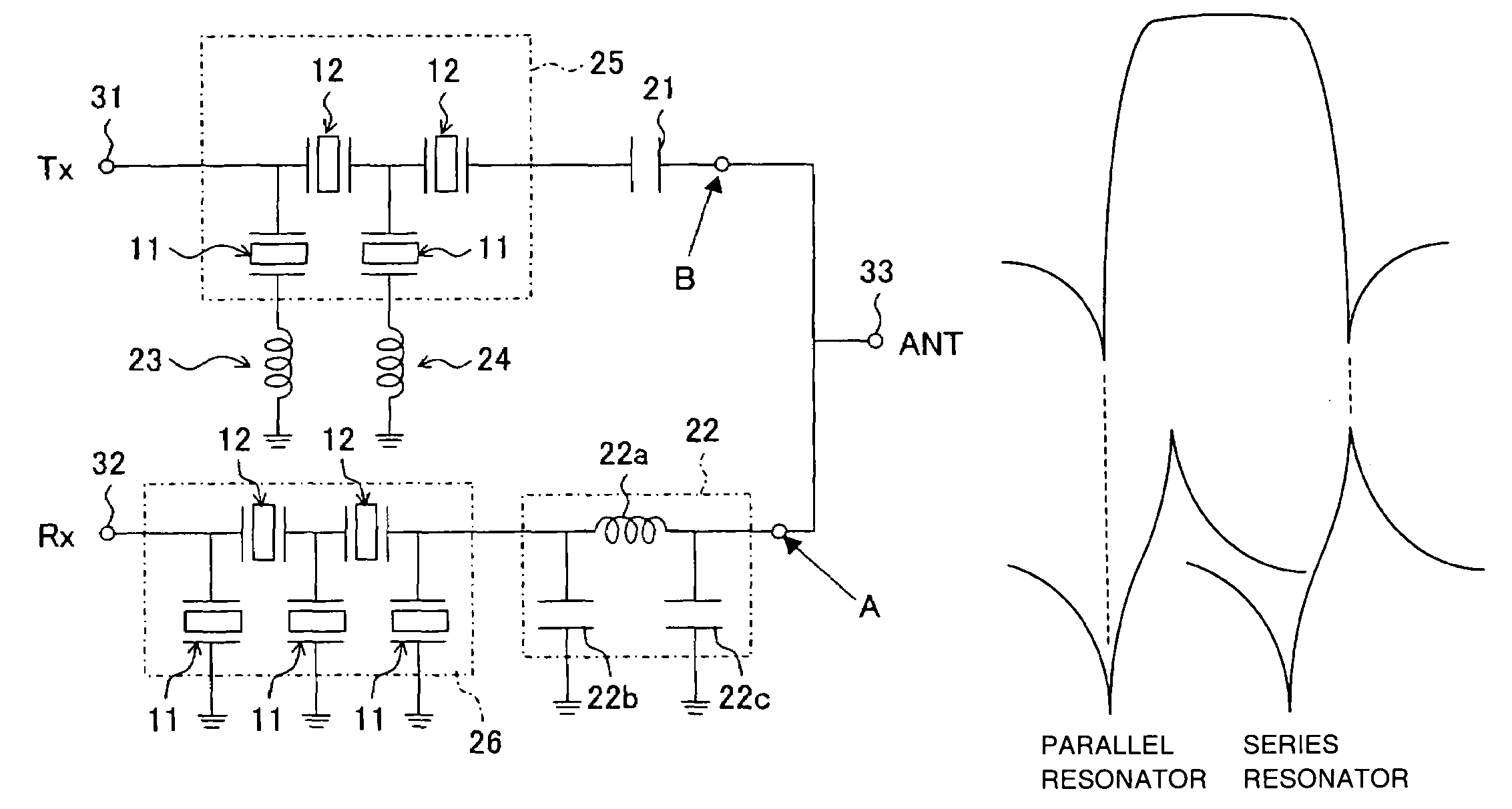
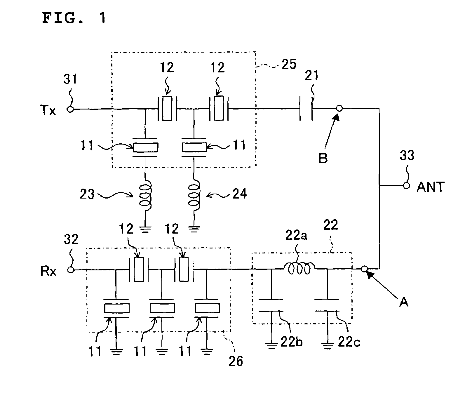
[0054]FIG. 1 shows the circuit diagram of a branching filter of a first preferred embodiment of the present invention. In the present preferred embodiment, the passband of a transmission-side filter (first filter) is preferably about 1850 MHz to 1910 MHz and the passband of a reception-side filter (second filter), which is set to be higher than the passband of the transmission-side filter, is preferably about 1930 MHz to 190 MHz. The filters constitute a PCS branching filter.

[0055]As shown in FIG. 1, the branching filter according to the present preferred embodiment preferably includes a transmission-side (Tx) terminal 31, a reception-side (Rx) terminal 32, and an antenna (ANT) terminal 33. The branching filter includes a transmission-side filter 25 provided between the antenna terminal 33 and the transmission-side terminal 31, a reception-side filter 26 provided between the antenna terminal 33 and the reception-side terminal 32, and a matching circuit 22 provided between the antenn...

second preferred embodiment

[0116]In a piezoelectric thin-film filter included in a branching filter according to a second preferred embodiment of the present invention, instead of the opening portion 1a and the concave portion described in the first preferred embodiment, as shown in FIG. 15, an acoustic reflective portion 43 is inserted between an Si substrate 44 corresponding to the Si substrate 1 and a vibrating portion formed on the Si substrate 44. The vibrating portion is a portion in which the piezoelectric thin film 4 is sandwiched between the lower electrode 3 and the upper electrode 5 in the same way as in the first preferred embodiment. The upper insulating film 6 may be further formed on the vibrating portion.

[0117]In the acoustic reflective portion 43, for example, AlN layers 43a and 43c and SiO2 layers 43b and 43d having acoustic impedances different from each other are alternately laminated to increase the reflectance ratio. In order to increase the reflectance ratio, in the alternately laminate...

third preferred embodiment

[0121]Next, in a communication device of a third preferred embodiment of the present invention, either of the ladder-type piezoelectric thin-film filters according to the first and second preferred embodiments or the above-described branching filters or any of the branching filters is mounted. A communication device is described with reference to FIG. 16. In the communication device 600, the receiver side (Rx side) for reception includes an antenna 601, an antenna-sharing portion / RF top filter 602, an amplifier 603, an Rx interstage filter 604, a mixer 605, a 1st IF filter 606, a mixer 607, a 2nd IF filter 608, a 1st and 2nd local synthesizer 611, a TCXO (temperature compensated crystal oscillator) 612, a divider 613, and local filter 614.

[0122]As is shown by a double line in FIG. 16, it is desirable to send a balanced signal from the Rx interstage filter 604 to the mixer 605 in order to secure the balancing.

[0123]Furthermore, the transmitter side (Tx side) for transmission in the c...


PUM


Abstract

A branching filter includes an antenna terminal, a transmission-side filter and a reception-side filter which are connected in parallel to the antenna terminal, and a matching circuit positioned between the antenna terminal and the reception-side filter. The reception-side filter is a ladder-type filter in which the frequency of a series resonator is higher than the antiresonant frequency of a parallel resonator. The transmission-side filter is a ladder-type filter and is the capacitance in the passband of the reception-side filter, and, because of the capacitance, the inductance of the impedance of the reception-side filter, when seen from the antenna terminal side, is reduced.

Description

BACKGROUND OF THE INVENTION[0001]1. Field of the Invention[0002]The present invention relates to a branching filter suitable for use in communication devices such as portable telephones, and also relates to a communication device including the branching filter.[0003]2. Description of the Related Art[0004]In recent years, the technological progress in miniaturization and weight reduction of communication devices such as portable telephones has been remarkable. In order to realize such progress, not only reduction and miniaturization of components constituting the communication devices, but also development of composite components having plural functions has been ongoing. In particular, a high-performance branching filter used in the RF stage is required.[0005]As a branching filter used in the RF stage as mentioned above, there is a branching filter using a ladder-type piezoelectric thin-film filter, as described in Japanese Unexamined Patent Application Publication No. 2001-24476 (pu...

Claims


Application Information

Patent Timeline
Patent Type & Authority Patents(United States)
IPC IPC(8): H03H9/00H03H9/54H03H9/17H03H9/72H03H9/56H03H9/58H03H9/70
CPCH03H9/564H03H9/706H03H9/568
Inventor KAWAMURA, HIDEKI
Owner MURATA MFG CO LTD
Why Eureka
Try Eureka