Directional acoustic alerting system

a technology of directional acoustic alerting and warning systems, which is applied in the direction of contact mechanisms, relays, instruments, etc., can solve the problems of loud and harsh sounds generated by such systems, the intended recipient may not be sufficiently compelled to react to the sound, and the sound generated by such systems is often not heard by the intended recipien

Inactive Publication Date: 2006-09-12
POMPEI FRANK JOSEPH
View PDF10 Cites 92 Cited by
  • Summary
  • Abstract
  • Description
  • Claims
  • Application Information

AI Technical Summary

Benefits of technology

[0009]In accordance with the present invention, an acoustic warning or alerting system is provided that may be employed to direct an audible warning signal to one or more intended recipients, while reducing the chance that the warning signal will be heard by others within the proximity of the system. Benefits of the acoustic alerting system are achieved by employing a parametric array of acoustic transducers that can generate beams of audible sound with much higher directivity than conventional audio sound sources.
[0011]In the presently disclosed embodiment, the parametric array of audio transducers operates by employing the nonlinear interaction between high frequency sound components, preferably in the ultrasonic frequency range, and the propagation medium to generate at least one beam of lower frequency sounds within the propagation medium. The result is a “virtual” sound source that is significantly larger than the wavelengths of the sounds generated by it. The larger the source of the sound, particularly in the axial direction (i.e., in the direction of propagation of the sound beam), the greater its directivity.
[0013]The presently disclosed directional acoustic alerting system may be employed as a replacement for conventional vehicle alerting systems such as horns, whistles, and bells to assure that primarily only those people and / or animals directly in front of the vehicle (even at significant distances away from the vehicle) hear the sound. As a result, louder and more attention-grabbing sounds may be generated by the acoustic alerting system without disturbing others within the proximity of the system.
[0016]By providing a directional acoustic alerting system that includes at least one parametric array of acoustic transducers as described above, audible warning signals can be generated that are heard primarily by the intended recipients of the signal (i.e., humans and / or animals), without unduly distracting others within the proximity of the system.

Problems solved by technology

However, conventional acoustic alerting systems such as horns, bells, whistles, and alarms have drawbacks in that the sound generated by such systems is often not heard by the intended recipients.
Even if the intended recipient hears the sound, he or she may not be sufficiently compelled to react to the sound in the most appropriate manner, such as by moving out of the path of an oncoming vehicle.
However, because conventional acoustic alerting systems are generally omnidirectional, the loud and harsh sounds generated by such systems can usually be heard not only by the intended recipients, but also by people who have no need to hear the sounds.
Specifically, when a train is travelling by a residential neighborhood, residents often complain about the loud warning sound of the train whistle as the train approaches road intersections, even though such warning signals are needed to avoid accidents.
As a result, the number of trains allowed to pass, as well as the number of allowable train transit hours, may be severely curtailed near such residential neighborhoods.
Similar drawbacks exist for automobile horns, which are generally intended to be heard only by people and / or animals in front of the automobile.
This can increase noise pollution to nuisance levels, especially in highly populated urban areas.

Method used


Image

  • Directional acoustic alerting system
  • Directional acoustic alerting system
  • Directional acoustic alerting system

Examples


Embodiment Construction

[0024]U.S. Provisional Patent Application No. 60 / 316,062 filed Aug. 30, 2001 entitled DIRECTIONAL ACOUSTIC ALERTING SYSTEM is incorporated herein by reference.

[0025]An acoustic warning or alerting system is disclosed that can direct at least one audible warning signal to one or more intended recipients, while minimizing the chance that the warning signal will be heard by others within the proximity of the system. The presently disclosed directional acoustic alerting system includes a parametric array of acoustic transducers configured to generate one or more beams of audible sound with a directivity that is significantly greater than that of audio sound generated using conventional acoustic warning or alerting techniques.

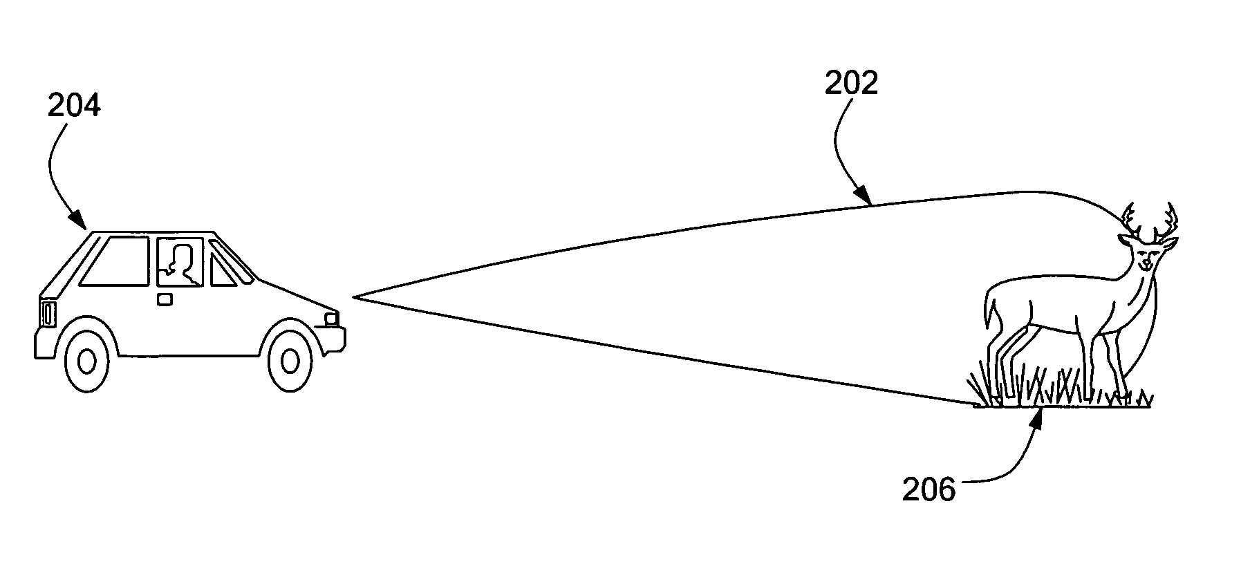
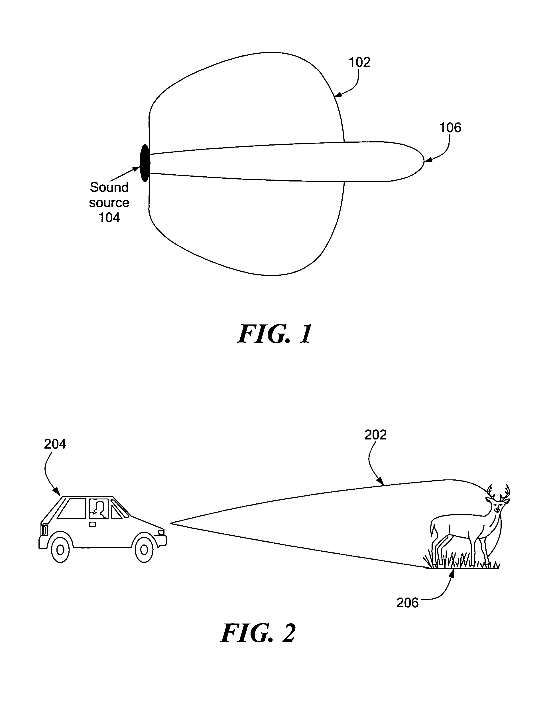
[0026]FIG. 1 depicts an illustrative distribution 102 of audio sound generated by a conventional acoustic warning or alerting system (not shown) at a sound source location 104, and an illustrative distribution 106 of a narrow audio beam generated by a directional ac...


PUM


Abstract

An acoustic warning or alerting system for directing an audible warning signal to at least one intended recipient, while reducing the chance that the warning signal will be heard by others within the proximity of the system. The system includes a modulator for modulating an ultrasonic carrier signal with a processed audio signal, a driver amplifier for amplifying the modulated carrier signal, and a parametric array of acoustic transducers for projecting the modulated and amplified carrier signal through a propagation medium for subsequent regeneration of the audio signal along a pre-selected projection path. The parametric array of audio transducers operates by employing the nonlinear interaction between high frequency sound components and the propagation medium to generate at least one highly directional beam of lower frequency sounds within the propagation medium. The directional acoustic alerting system may be employed as a replacement for conventional alerting systems such as horns, whistles, and bells to assure that primarily only those people and / or animals intended to hear the warning signal actually hear the sound.

Description

CROSS REFERENCE TO RELATED APPLICATIONS[0001]This application claims priority of U.S. Provisional Patent Application No. 60 / 316,062 filed Aug. 30, 2001 entitled DIRECTIONAL ACOUSTIC ALERTING SYSTEM.STATEMENT REGARDING FEDERALLY SPONSORED RESEARCH OR DEVELOPMENT[0002]N / ABACKGROUND OF THE INVENTION[0003]The present invention relates generally to acoustic warning or alerting systems, and more specifically to acoustic warning or alerting systems capable of producing highly directional audible sound.[0004]Acoustic warning or alerting systems have been widely employed in a variety of applications. For example, acoustic alerting systems have been employed in vehicles such as automobiles, railroad trains, bicycles, airplanes, and boats for generating sounds to alert people and / or animals of the vehicle's presence. Specifically, horns have been used in automobiles for altering pedestrians of the automobile's approach. Further, horns, bells and / or whistles have been used on trains for alterin...

Claims


Application Information

Patent Timeline
Patent Type & Authority Patents(United States)
IPC IPC(8): G08B3/10
CPCG08B3/10A01M29/18
Inventor POMPEI, FRANK JOSEPH
Owner POMPEI FRANK JOSEPH
Why Eureka
Try Eureka