Compact antenna device

Inactive Publication Date: 2006-09-12
ALPS ALPINE CO LTD
View PDF14 Cites 11 Cited by
  • Summary
  • Abstract
  • Description
  • Claims
  • Application Information

AI Technical Summary

Benefits of technology

[0010]Aspects of the present invention thus provide a high-performance antenna device with

Problems solved by technology

In the antenna device 1 and the antenna device 5, therefore, it is difficult to reduce the antenna height while

Method used


Image

  • Compact antenna device
  • Compact antenna device
  • Compact antenna device

Examples


Embodiment Construction

[0022]The embodiments of the present invention will be described with reference to drawings.

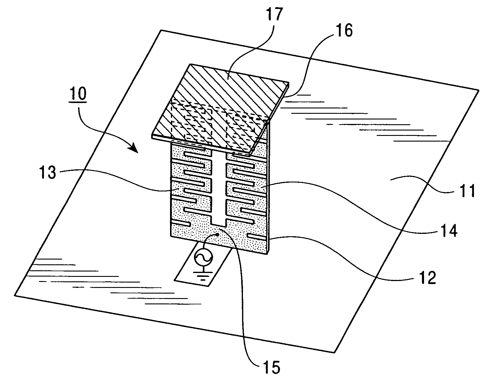
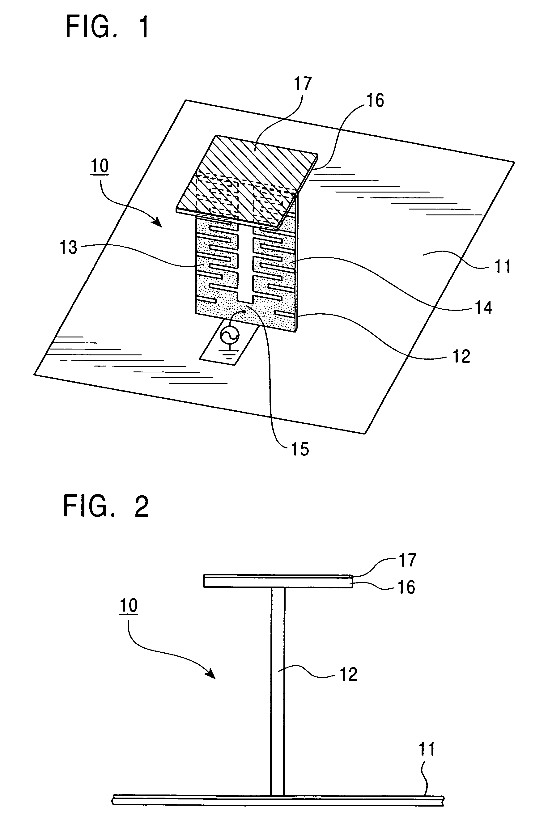
[0023]FIG. 1 is a perspective view of a single-band antenna device according to an embodiment of the present invention, and FIG. 2 is a side view of the antenna device.

[0024]In an antenna device 10 shown in these figures, a first radiating conductor 13 and a second radiating conductor 14 are made of, for example, copper foil. The first and second radiating conductors 13, 14 are meandering and are symmetrically disposed on a surface of a dielectric substrate 12 that is placed upright on a ground conductor 11. This is to say that the dielectric substrate 12 is disposed on the ground conductor 11 such that the dielectric substrate 12 extends in a direction substantially perpendicular to the direction in which the ground conductor 11 extends. Lower ends of the first radiating conductor 13 and the second radiating conductor 14 are connected at a junction 15. A power feeder such as a coaxial cable ...


PUM


Abstract

An antenna includes a dielectric substrate disposed on a ground conductor and first and second radiating conductors containing meandering lines that are symmetrically disposed on a surface of the dielectric substrate and whose lower ends are connected at a junction. A third radiating conductor is disposed between the first radiating conductor and the second radiating conductor and extends in a straight line along the symmetry axis of both the radiating conductors. A capacitive conductor is disposed on the dielectric substrate and is substantially parallel to the ground conductor. The upper ends of the first, second and third radiating conductors are connected to the capacitive conductor. Power of a frequency supplied to the junction causes the first and second radiating conductors to resonate while power of a higher frequency causes the third radiating conductor to resonate.

Description

BACKGROUND OF THE INVENTION[0001]1. Field of the Invention[0002]The present invention relates to antenna devices suitable for being incorporated into in-vehicle telecommunication systems and the like.[0003]2. Description of the Related Art[0004]As shown in FIG. 5, an antenna device having a meandering radiating conductor patterned on a substrate is known as a compact antenna with a reduced height for being incorporated into an in-vehicle telecommunication system and the like (see, e.g., Japanese Unexamined Patent Application Publication No. 2000-349532 (in particular, pages 3 to 4, FIG. 1)).[0005]In an antenna device 1 shown in FIG. 5, a meandering radiating conductor 3 made of copper foil is formed on a surface of a dielectric substrate 2 that is placed upright on a ground conductor 4, and high-frequency power is supplied to the lower end of the radiating conductor 3 via a power feeder such as a coaxial cable. As compared to the height of a radiating conductor formed in a straight ...

Claims


Application Information

Patent Timeline
IPC IPC(8): H01Q1/38H01Q1/32H01Q21/30H01Q5/10H01Q5/371H01Q9/36H01Q9/40H01Q9/42
CPCH01Q1/3291H01Q1/38H01Q5/378H01Q9/40H01Q9/36
Inventor YUANZHU, DOU
Owner ALPS ALPINE CO LTD
Why Eureka
Try Eureka