
Omni-azimuthal pattern generator for VLF and LF communication

a technology of omniazimuthal pattern generator and lf communication, applied in the field of antennas, can solve the problems of user having to retune the circuit, and the antenna is rendered blind, and achieves the effect of good reception

Active Publication Date: 2006-09-12
THE UNITED STATES OF AMERICA AS REPRESENTED BY THE SECRETARY OF THE NAVY
View PDF5 Cites 3 Cited by
  • Summary
  • Abstract
  • Description
  • Claims
  • Application Information

AI Technical Summary

Benefits of technology

[0009]It is a general purpose and object of the present invention to generate an antenna pattern that does not change as a function of azimuth angle, but has equally good reception from all azimuth angles.

Problems solved by technology

This null renders the antenna “blind” along that axis.
The disadvantage is that over a broad range of frequencies the user has to retune the circuit every time the frequency of operation changes.

Method used


Image

  • Omni-azimuthal pattern generator for VLF and LF communication
  • Omni-azimuthal pattern generator for VLF and LF communication
  • Omni-azimuthal pattern generator for VLF and LF communication

Examples


Embodiment Construction

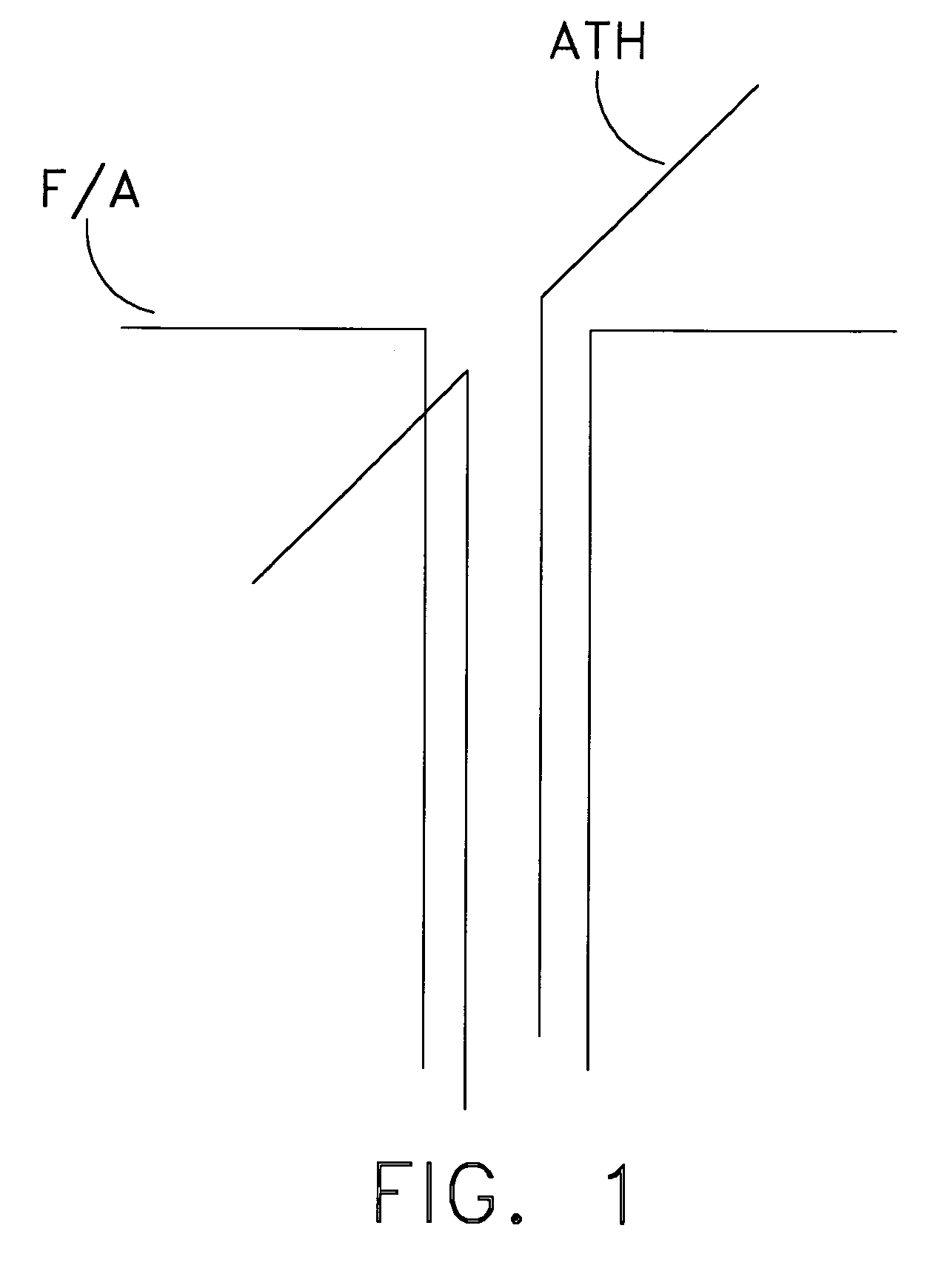
[0019]The omni-azimuthal pattern generator is designed to work with the AN / BRA-34 (V) and OE-538 / BRC VLF / LF loop antennas. It is not, however, limited as such and can be scaled and applied to other frequency ranges of interest. Inside each of these antennas are two identical orthogonally mounted loop antennas, called the “Fore / Aft” (F / A) and “Athwart” (ATH) loops. Referring now to FIG. 1 the equivalent representation of the identical orthogonal antennas F / A and ATH is illustrated. The outputs of each of these antennas is amplified in the antenna housing and presented as a balanced twisted pair transmission line.

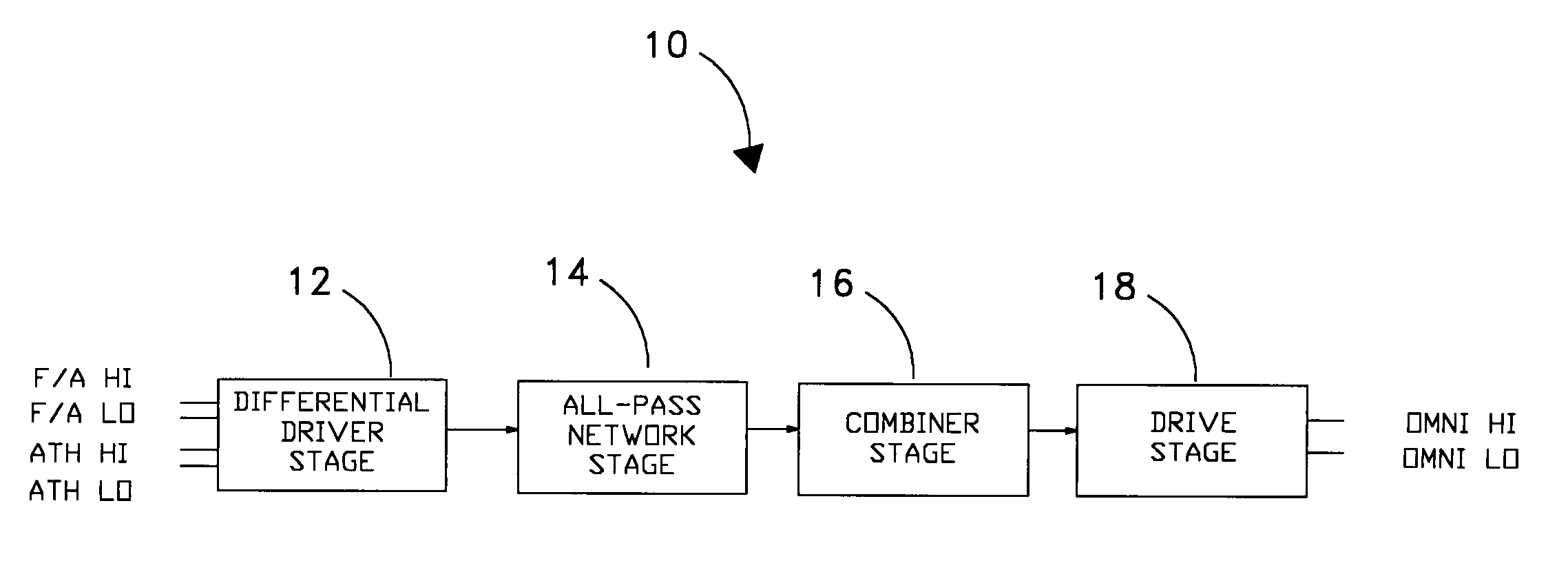
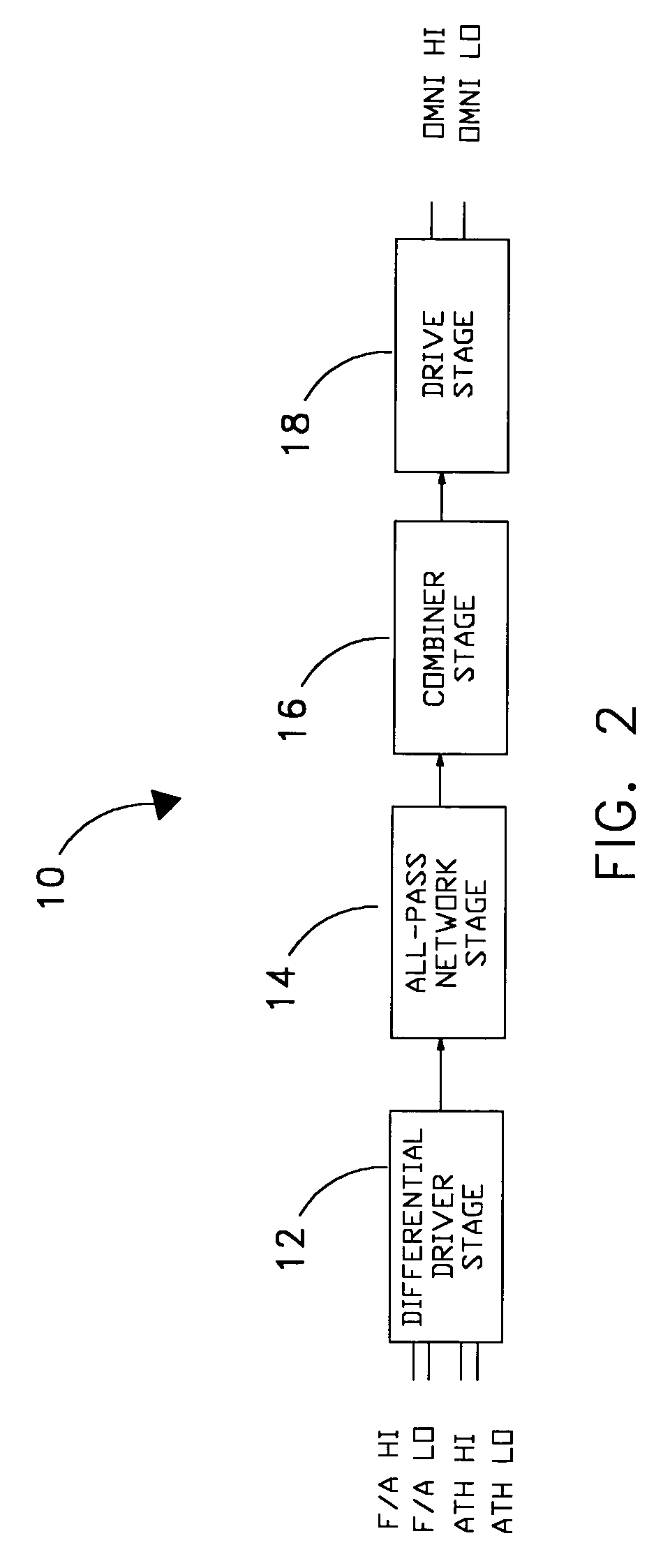
[0020]Referring now to FIG. 2, there is illustrated a block diagram of the four stages of the omni-azimuthal pattern generator 10. The first stage is the differential driver stage 12. The two balanced twisted pair transmission lines from the orthogonal antennas F / A and ATH enter the omni-azimuthal pattern generator 10 at the differential driver stage 12 at the points denoted ...


PUM


Abstract

A relative phase shift is induced in the signals of a pair of identical orthogonal antennas such that when the signals are combined the signals are 90 degrees out of phase. This is done in order to eliminate the null along the axis between the two dipole moments of the antennas such that the system has equally good reception from all azimuth angles over a broad range of frequencies. The phase shift is accomplished with the use of single pole operational amplifier circuits whose pole frequencies are adjusted by means of a potentiometer prior to implementation of the antenna system.

Description

STATEMENT OF GOVERNMENT INTEREST[0001]The invention described herein may be manufactured and used by or for the Government of the United States of America for governmental purposes without the payment of any royalties thereon or therefore.CROSS REFERENCE TO OTHER RELATED APPLICATIONS[0002]Not applicable.BACKGROUND OF THE INVENTION[0003](1) Field of the Invention[0004]The present invention relates to antennas, and more specifically to the elimination of the null along the axis coincident with the dipole moment of an antenna.[0005](2) Description of the Prior Art[0006]Electrically small antennas possess a pattern in azimuth that has a null along an axis coincident with the dipole moment of the antenna. This null renders the antenna “blind” along that axis. If two antennas are used and the signals are combined, a null occurs along an axis between the two dipole moments. An ideal antenna system would be one capable of rendering equally good reception from all azimuth angles without a nu...

Claims


Application Information

Patent Timeline
Patent Type & Authority Patents(United States)
IPC IPC(8): H01Q9/16
CPCH01Q21/26
Inventor TONN, DAVID A.
Owner THE UNITED STATES OF AMERICA AS REPRESENTED BY THE SECRETARY OF THE NAVY
Learn More