Color display device

a display device and color display technology, applied in the direction of luminescnet screens, identification means, instruments, etc., can solve the problems of limited use of the display device, inability to display full color, and increase in power consumption

Inactive Publication Date: 2006-09-12
CITIZEN WATCH CO LTD
View PDF16 Cites 43 Cited by
  • Summary
  • Abstract
  • Description
  • Claims
  • Application Information

AI Technical Summary

Benefits of technology

[0022]It is an object of the present invention to at least solve the problems in the conventional technology.

Problems solved by technology

Thus, a mechanical component, such as a motor that rotates the filters, is required which results up-sizing and increase in power consumption.
However, a full-color display is impossible in this color display until the blue LED was not developed.
Thus, the major use of this display device is limited in multicolored display of around four colors on a simple guideplate, for example.
Such color variation may cause subtle color differences from LED to LED even if the colors of the emitted lights are identical.
Nevertheless, there is a problem because of difficulty to keep the chromaticity of the white level unchanged.
It is therefore difficult to equalize the chromaticity of white levels in different display devices.
Accordingly, it is extremely difficult to adjust the white level.
Even if differences in chromaticity of the white level among plural displays can be adjusted at the steps of producing the displays, temperature dependence present in a luminous intensity characteristic of each LED causes the following problem.
Each LED is different from others in power consumption and in amount of heat, however.
Accordingly, even if the additional temperature compensator is provided, it is difficult to effectively suppress temperature fluctuations.
The need of individual non-linear compensations for fluctuations and the presence of variations in luminous intensities cause a problem of complex and large temperature compensators.
Each LED is individually different in lifetime and durability and accordingly has a problem that the white level is varied in a long term.
This is not disadvantageous, however, if the use is not for a long time.
In particular, even if LEDs of red, green, and blue are turned on sequentially to create white using the action of integration along time-axis at human eyes, it is extremely important and difficult to keep the chromaticity of the white level unchanged.

Method used


Image

  • Color display device
  • Color display device
  • Color display device

Examples


Embodiment Construction

[0048]Exemplary embodiments of the display device of the present invention will now be explained in detail with reference to the accompanying drawings.

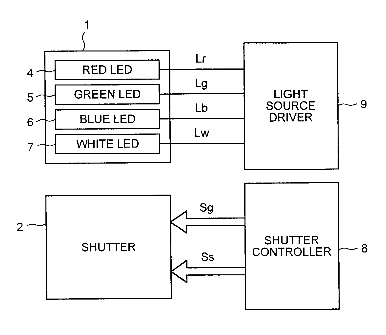
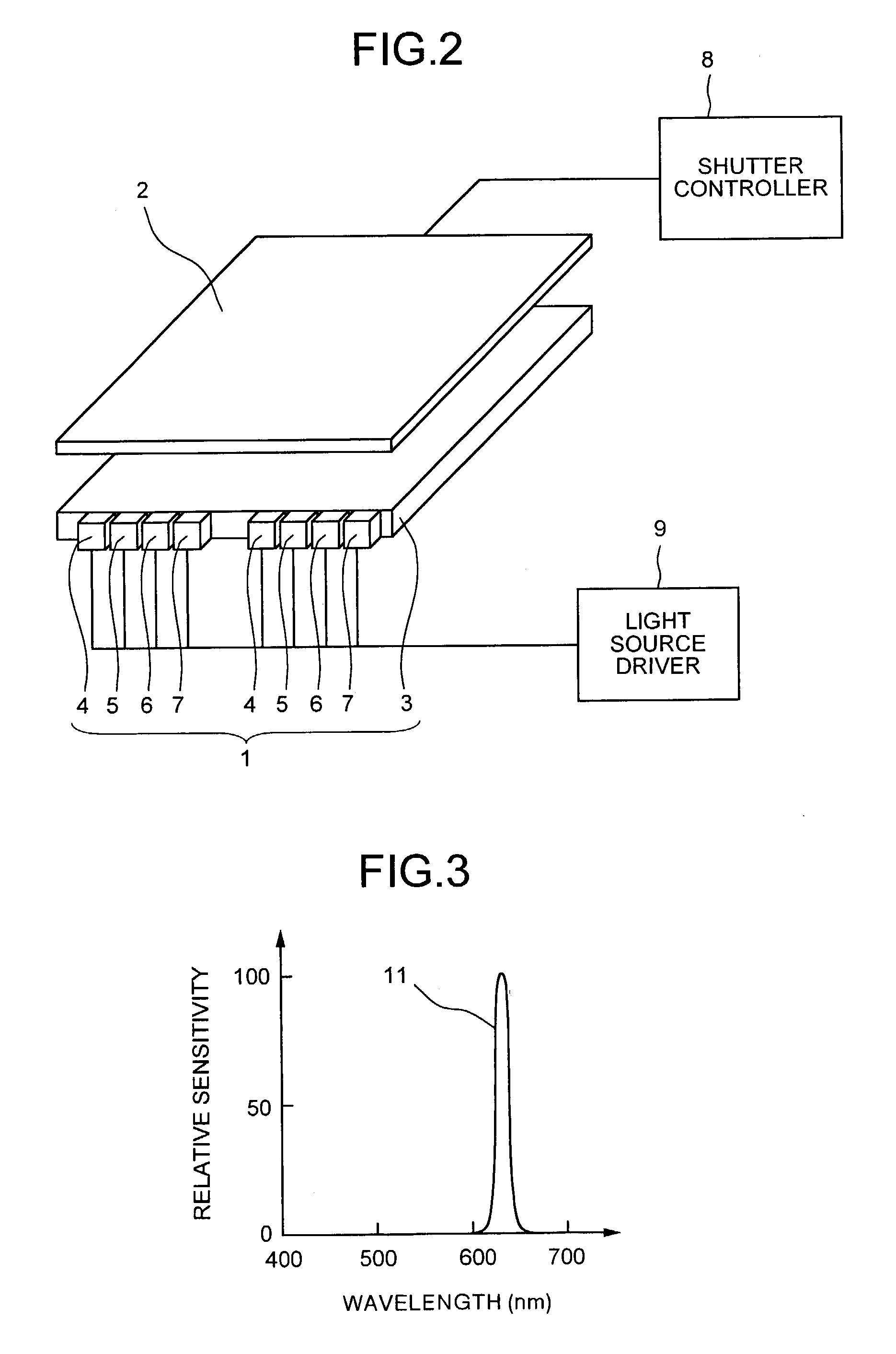
[0049]FIG. 2 schematically shows the configuration of a display device according to an embodiment of the present invention. This display device comprises a light source 1 that includes a plurality of independently controllable color light sources that emit lights having different spectral characteristics.

[0050]It is assumed here that the display device is a full-color display device. The light source 1 includes a plurality (two are shown in the diagrams) of red LEDs 4, a plurality (two are shown in the diagrams) of green LEDs 5, a plurality (two are shown in the diagrams) of blue LEDs 6, and a plurality (two are shown in the diagrams) of white LEDs 7 at the side of a light guide plate 3. There is no limit to the number of the LEDs of each color, although at least one while LED is required. A light source driver 9 drives the light sour...


PUM

PropertyMeasurementUnit
wavelengthaaaaaaaaaa

Abstract

In a field sequential display device, a desired chromaticity of the white level can be easily achieved and fluctuations in the white level caused by fluctuation factors such as temperature characteristics can be suppressed. A light source comprises red, green, and blue LEDs and a white LED. The white LED includes a blue LED covered with a yellow fluorescent material. One field is divided into display subfields of red, green, blue and white. Only the red LED turns on in the red display subfield, only the green LED turns on in the green display subfield, only the blue LED turns on in the blue display subfield, and only the white LED turns on in the white display subfield. A shutter is controlled in each subfield based on sub-image data of each color.

Description

BACKGROUND OF THE INVENTION[0001]1) Field of the Invention[0002]The present invention relates to a field sequential color display device that achieves multicolored display by dividing a field into a plurality of subfields, displaying a different color image in each subfield, and subjecting different color images to color mixture through the action of integration along time-axis at human eyes.[0003]2) Description of the Related Art[0004]Several types of field sequential display devices are known. For example, one type of the field sequential display device (see Japanese Patent Application Laid-Open No. 7-333574) is provided with a light source that emits a light with broadband wavelengths, or a white light; and a disc filter that includes a plurality of filters for respectively transmitting red (R), green (G), and blue (B) lights. When the disc filter is rotated, a wavelength zone for transmitting a light is sequentially switched to another on a subfield basis.[0005]Another type of t...

Claims


Application Information

Patent Timeline
Patent Type & Authority Patents(United States)
IPC IPC(8): H01L33/00G02F1/133G02F1/13357G09F9/00G09G3/20G09G3/34G09G3/36H01L27/32H01L33/02H01L33/50H01L33/56
CPCG09G3/3413G09G3/3607H01L27/3213G02F2001/133622G09G2310/0235G09G2310/08G09G2320/0633G09G2320/064G09G2320/0666G09G2340/06G09G2360/145G09G2320/0242G02F1/133622H10K59/351
Inventor AKIYAMA, TAKASHI
Owner CITIZEN WATCH CO LTD
Why Eureka
Try Eureka