Optical scanner and image forming apparatus

an image forming apparatus and optical scanner technology, applied in the field of optical scanners and image forming apparatuses, can solve the problems of forming time and parts cost increase, shading and ghost light have not been taken into account, and the image thickness of the thickened beam spot diameter is not good, so as to achieve the effect of reducing the cost of parts and forming tim

Inactive Publication Date: 2006-09-12
RICOH KK
View PDF51 Cites 71 Cited by
  • Summary
  • Abstract
  • Description
  • Claims
  • Application Information

AI Technical Summary

Problems solved by technology

However, the scanning lens using the conventional special toric surface, as described in (1), is a scanning lens in which the opposite surfaces are both anamorphic surfaces, and hence there are problems to be solved in that:beam spot diameter thickening occurs due to decentering; andwhen the special toric surface is used for a surface having a large angle of inclination, machining accuracy deteriorates, thereby causing a defective image having thickened beam spot diameter due to a form error such as swells, or vertical lines.
In the scanning lens using the conventional special toric surface, as described in (1) and (2), the lens is thick, and even if the lens is a plastic molded article, the forming time and the cost of parts increase.
Further, shading and ghost light have not been taken into consideration.

Method used


Image

  • Optical scanner and image forming apparatus
  • Optical scanner and image forming apparatus
  • Optical scanner and image forming apparatus

Examples


first embodiment

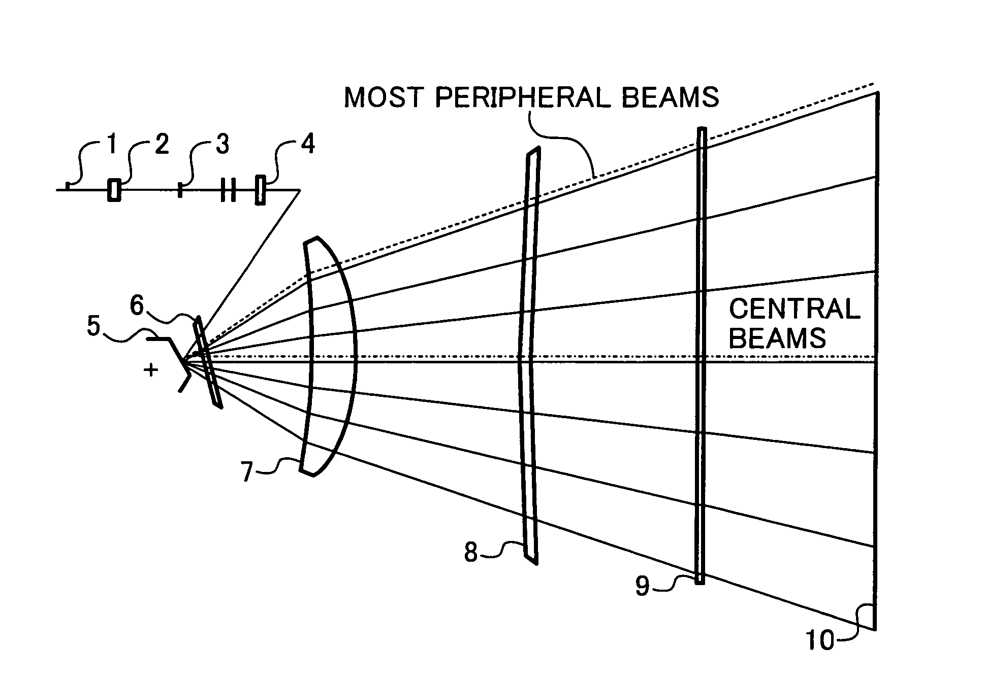
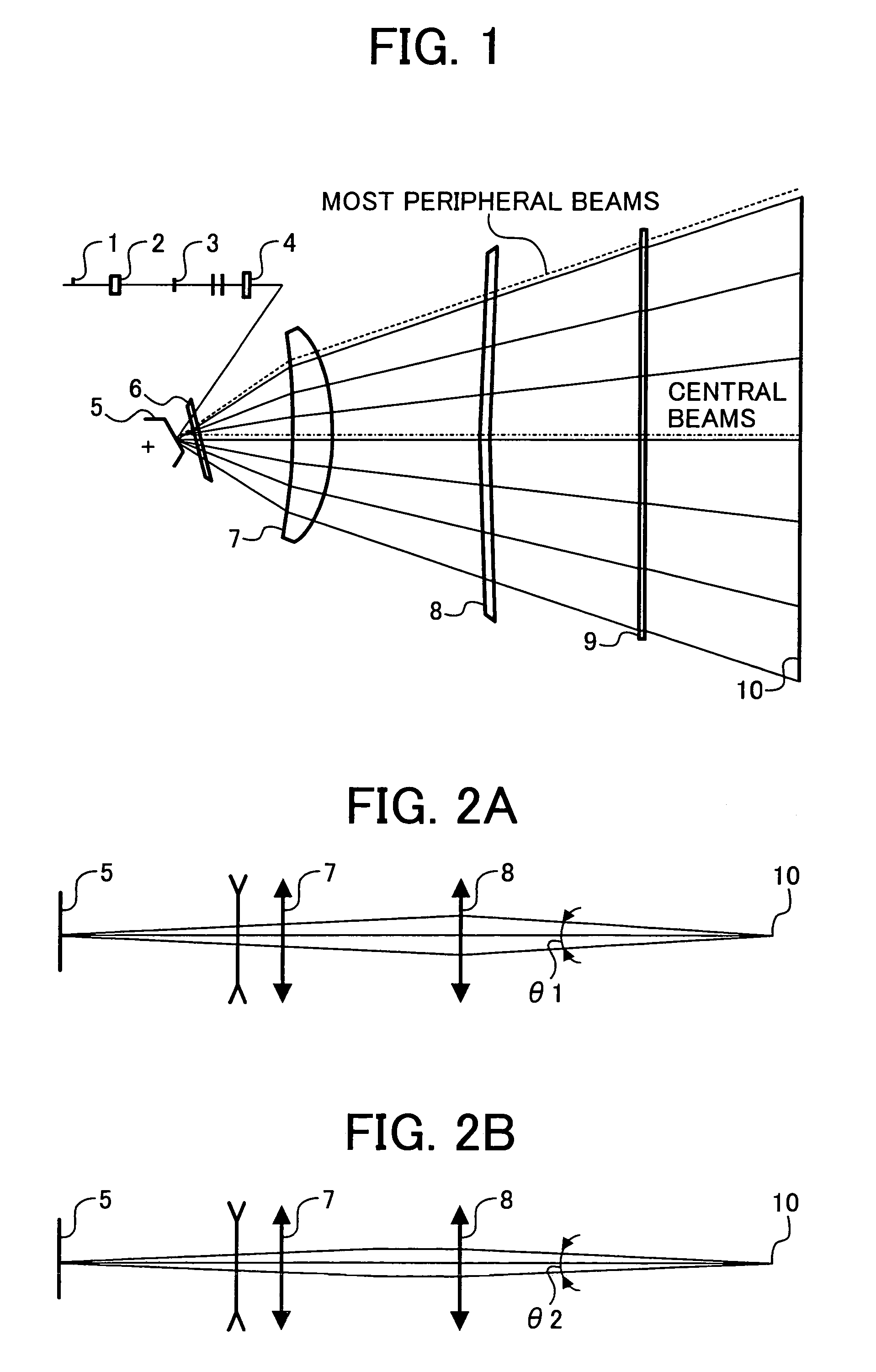
[0041]FIG. 1 illustrates an optical scanner according to a A light source 1 in the optical scanner includes a semiconductor laser, and for example, may be a multi-beam light source in which a plurality of light emitting sources are arranged at an equal interval. The beams emitted from the light source 1 are divergent beams, and are coupled into an optical system thereafter by a coupling lens 2 that constitutes an optical coupler of the present invention. The beams coupled by the coupling lens 2 may be weak divergent beams or weak convergent beams, or parallel beams. The beams are subjected to beam forming by an aperture 3, and the beams converge only in the vertical scanning direction by the action of a cylindrical lens 4. Therefore, a line image of the beams, longer in the horizontal scanning direction than in the vertical scanning direction, is formed at a position close to a deflection reflecting surface of a polygon mirror 5, being a deflector. The cylindrical lens 4 and the po...

second embodiment

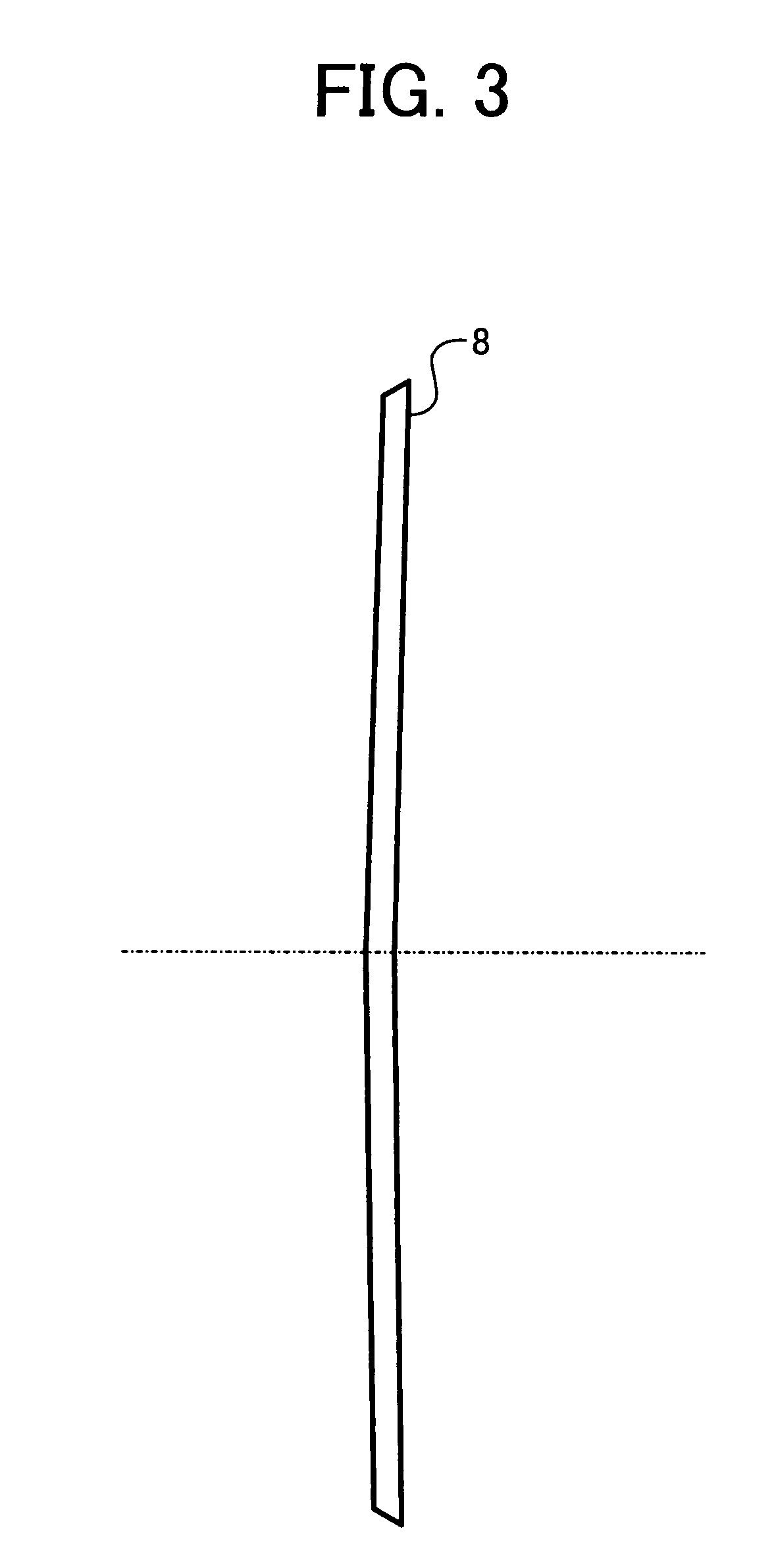
[0056]Japanese Patent Application Laid-Open No. 2001-21824 discloses a method of decreasing the angle between the incident beams and the scanning lens. However, in this method, it is necessary to largely curve the scanning lens within the deflection surface of revolution. Consequently, the workability of the scanning lens decreases, and the tolerance for decentering considerably decreases. Therefore, in the second embodiment, the power in the vertical scanning direction on the first surface of the second scanning lens 8 is made positive, so that the wavefront aberration occurring on the first surface of the first scanning lens 7 is compensated by the first surface of the second scanning lens 8.

[0057]If the first scanning lens 7 has a meniscus shape with the concave directed toward the polygon mirror in the horizontal scanning direction, as shown by two-dot chain line in FIG. 10, then there is the possibility that the ghost light reflected from the first surface of the second scannin...

third embodiment

[0058]The optical scanner will be explained next. In this embodiment, the appearance is the same as those shown in FIGS. 1, 9A and 9B. The scanning optical system includes a plurality of scanning lenses 7 and 8. The first scanning lens 7 closest to the deflector has a meniscus shape, which is concave toward the deflector side in the horizontal scanning direction. The first surface of the scanning lens 7 that is closest to the deflector has a negative power in the vertical scanning direction, and is the special toric surface in which the radius of curvature in the vertical scanning decreases from the optical axis of the lens surface toward the periphery of the horizontal scanning direction, and increases bordering on an extreme value. The first surface of the second scanning lens 8 farthest from the deflector has a convex shape toward the deflector side in the horizontal scanning direction, and the second scanning lens 8 farthest from the deflector has a negative power in the horizo...


PUM


Abstract

An optical scanner includes a light source, an optical coupler, an optical line image unit, a deflector, and an optical scanning unit. The optical scanning unit includes scanning lenses that guide the beams to a surface to be scanned. A surface on the deflector side of the scanning lens closest to a deflection reflecting surface has a negative power in a vertical scanning direction, and is a special toric surface in which a radius of curvature in a vertical scanning changes from an optical axis of the lens surface toward a periphery of the horizontal scanning direction. An F number of the beams toward the surface to be scanned of the scanning lens in the vertical scanning direction is larger in a peripheral part than in a central part in an effective scanning width.

Description

CROSS-REFERENCE TO RELATED APPLICATIONS[0001]The present document incorporates by reference the entire contents of Japanese priority document, 2003-167508 filed in Japan on Jun. 12, 2003.[0002]Further, the present document incorporates by reference the entire contents of Japanese priority document, 2003-374378 filed in Japan on Nov. 4, 2003.BACKGROUND OF THE INVENTION[0003]1) Field of the Invention[0004]The present invention relates to an optical scanner and an image forming apparatus that can be used in a laser beam printer (LBP), a digital copier, a plain paper facsimile (PPF), and the like.[0005]2) Description of the Related Art[0006]In recent electrographic image forming apparatus such as a laser printer, densification of the image formed is speedy. To realize densification of the formed image, it is necessary to realize a small beam spot diameter for optical scanning on an image forming surface of an image carrier such as a photoconductor. The demand for such an optical scanner...

Claims


Application Information

Patent Timeline
Patent Type & Authority Patents(United States)
IPC IPC(8): G02B26/08G02B26/12
CPCG02B26/125
Inventor HAYASHI, YOSHINORIATSUUMI, HIROMICHIIZUMI, YASUTAKA
Owner RICOH KK
Why Eureka
Try Eureka