Method and system for link fabric error detection and message flow control

Inactive Publication Date: 2006-09-12
NXP USA INC +1
View PDF11 Cites 40 Cited by
  • Summary
  • Abstract
  • Description
  • Claims
  • Application Information

AI Technical Summary

Benefits of technology

[0020]Further aspects of the invention provide a digital data system as described above in which the control symbol includes status information indicating the availability of ports, processing resources or packet buffers in the second node. Such information can be used by the first node to regulate its transmission rate efficiently to the available receiving resources without deadlock.
[0021]In accordance with a further aspect of the invention, control symbols used to acknowledge received packets may be specially-delineated to optimize flow or integrity at the link level, i.e., between adjacent nodes and/or elements in the interconnect fabric. These acknowledgement

Problems solved by technology

As a result, the endpoint devices are not tied up awaiting completion of a transa

Method used


Image

  • Method and system for link fabric error detection and message flow control
  • Method and system for link fabric error detection and message flow control
  • Method and system for link fabric error detection and message flow control

Examples


Example

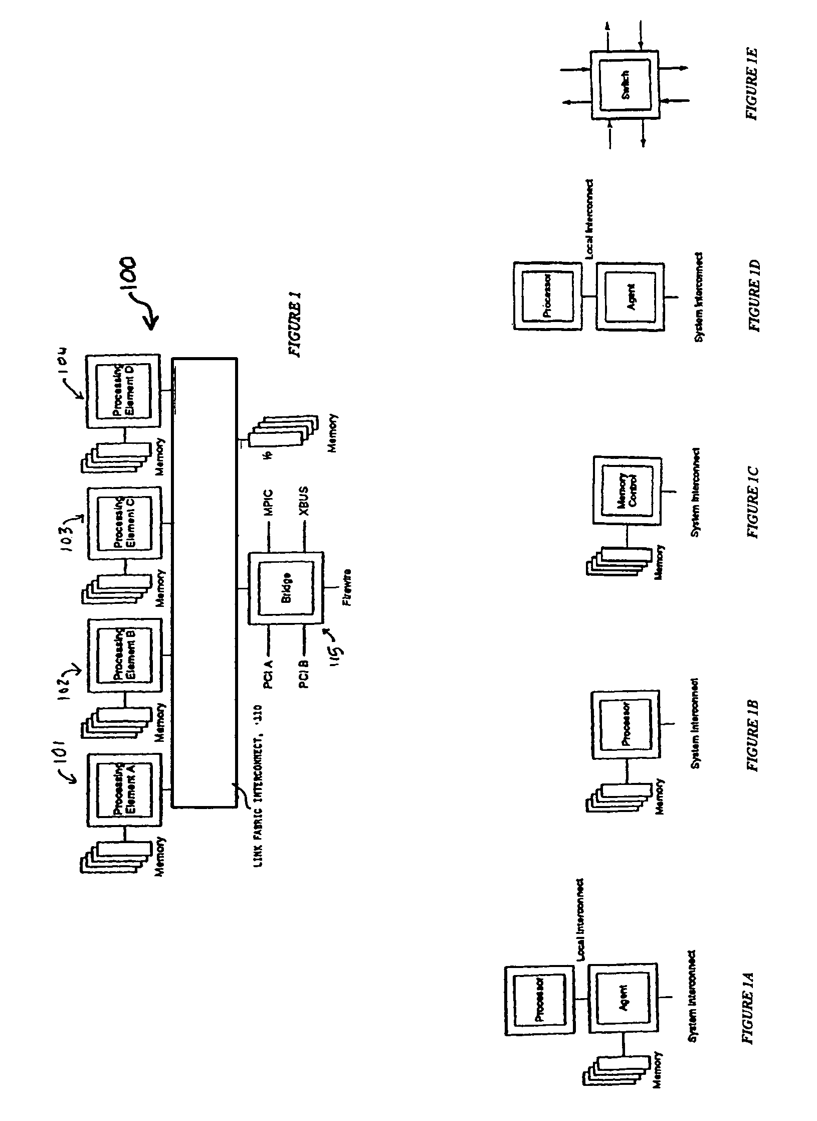
[0045]Architecture and Interconnect Fabric FIG. 1 illustrates generally an embodiment of a digital data system 100 employing link interconnect message communication in accordance with the present invention. The system includes a plurality of nodes, some of which are shown as digital devices 101, 102, 103, 104, . . . In the illustrated embodiment, these are processors with associated memories, though, they may also comprise other digital devices capable of generating, handling and / or passing message packets.

[0046]In this regard, it will be understood that messaging over interconnected links as described herein has wide application, e.g., to systems that implement direct memory access, to systems that provide communications between processors in a domain, as well as to systems that provide such communications between lower-level digital devices or components. Examples of the former are provided by FIGS. 1 and 1A. Examples of the latter are provided by FIGS. 1B and 1D (a stand-alone pr...


PUM


Abstract

A digital data system employs multiple error protection mechanisms on messages that pass along a link interconnect fabric from one node or device to another node or device. The nodes may be end points (such as processor or storage units), or may be intermediate devices or branch points (such as routers or switches in the interconnect fabric). The interconnect fabric comprises a set of one or more routers, switches, electrical, optical, electroptical or other links along which messages are passed. Messages are packets having a defined format including, e.g., a header portion, typically with source and target addresses, and codes indicating message-type or other information, followed by one or more data or other fields. A first node (“sending” node) of a digital data system as described sends a data transmission comprising one or more message packets to a second node (“receiving” node) over a link of a fabric as described above. The receiving node returns a control symbol to the sending node for each packet received on the link. The sender uses information in that symbol to control the further transmission of message packets to receiver over the link.

Description

REFERENCE TO RELATED APPLICATIONS[0001]This application claims the benefit of priority of U.S. Provisional Patent Application Ser. No. 60 / 175,856, filed Jan. 13, 2000, entitled “Rio Bus Protocol,” the entirety of the teachings of which are incorporated by reference.BACKGROUND OF THE INVENTION[0002]The current development of computer and embedded systems is burdened by divergent requirements. On one hand performance is expected to increase exponentially, while on the other hand the price of components is driven by market factors to continuously decrease. Developers are burdened with the challenge of increasing device density, or functional density, while decreasing the board space and ultimately the floor space that the components require. The physics of signal handling and transmission, and the need for standardized interconnects and scalable systems, impose further bounds on system development.[0003]Many existing computer systems are built around a single high-speed common bus. Whe...

Claims


Application Information

Patent Timeline
IPC IPC(8): H04L12/28H04L12/56
CPCH04L1/0061H04L1/0072H04L1/1806H04L41/0681H04L1/1887H04L2001/0094H04L12/4641
Inventor FRISCH, ROBERT C.MARIETTA, BRYAN D.BOUVIER, DANIEL L.
Owner NXP USA INC
Why Eureka
Try Eureka