Vehicle-mounted meter system

a meter system and vehicle-mounted technology, applied in the field of meter systems, can solve the problems of increasing the development cost, reducing the flexibility of the design of the combination meter, and the minimization of the development cost, so as to simplify the layout, facilitate the rewriting of the computer, and facilitate the handling

Inactive Publication Date: 2006-09-12
YAZAKI CORP
View PDF12 Cites 9 Cited by
  • Summary
  • Abstract
  • Description
  • Claims
  • Application Information

AI Technical Summary

Benefits of technology

[0053]Preferably, the control unit is a card-typed one, which can be handled with ease.
[0054]Preferably, the card-typed unit is a PC card in which a software program can be easily rewritten by a computer.
[0055]In the first and second aspects of the invention, the data inputting and outputting circuit is arranged on the meter main body as an independent circuit, while the control circuit is arranged on the control unit detachably attached to the meter main body. Thus, the circuit board mounted on the meter main body is simplified in layout without a control circuit, decreasing a manufacturing cost. Furthermore, the control unit separately arranged from the meter main body, allowing standardized multi-types of control units having different functions even for a combination meter of a higher quality.
[0056]In the third to fifth aspects of the invention, vehicle-mounted meter systems are designed so as to have a common part or device to decrease a development cost of the vehicle-mounted meter systems. Furthermore, the meter main body can have an indication pattern to comply with user's request, and many types of vehicle-mounted meter systems even of a high grade or design can be provided with a less cost.

Problems solved by technology

Thus, the combination meter requires a special design for each application, increasing a development cost.
Or, minimization of the development cost decreases flexibility of meter design.
Furthermore, when multi-display design with LEDs is applied for a combination meter, users cannot select freely the design of the combination meter, because the meter is specifically designed for each car.

Method used


Image

  • Vehicle-mounted meter system
  • Vehicle-mounted meter system
  • Vehicle-mounted meter system

Examples


Embodiment Construction

[0071]Referring to the accompanied drawings, embodiments of a vehicle-mounted meter system according to the present invention will be discussed.

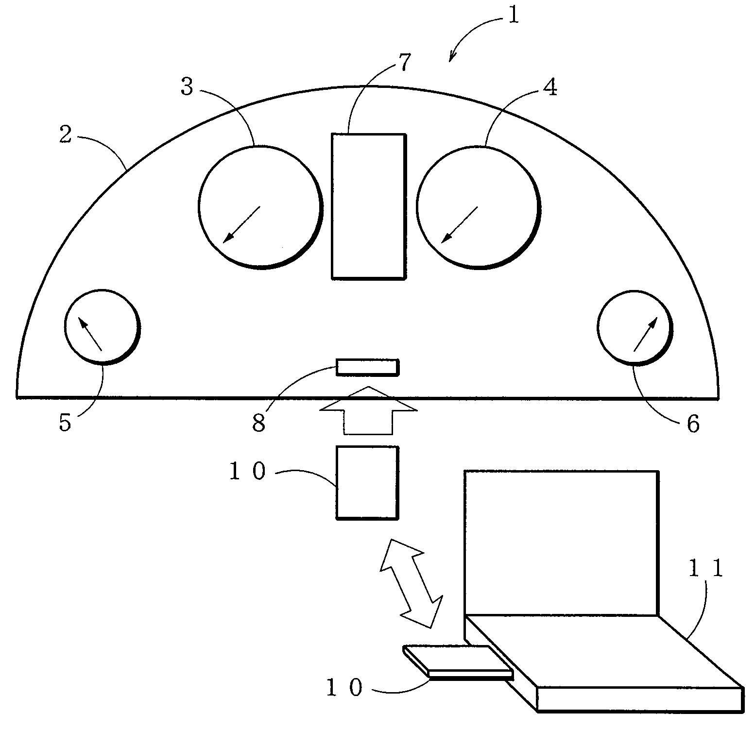
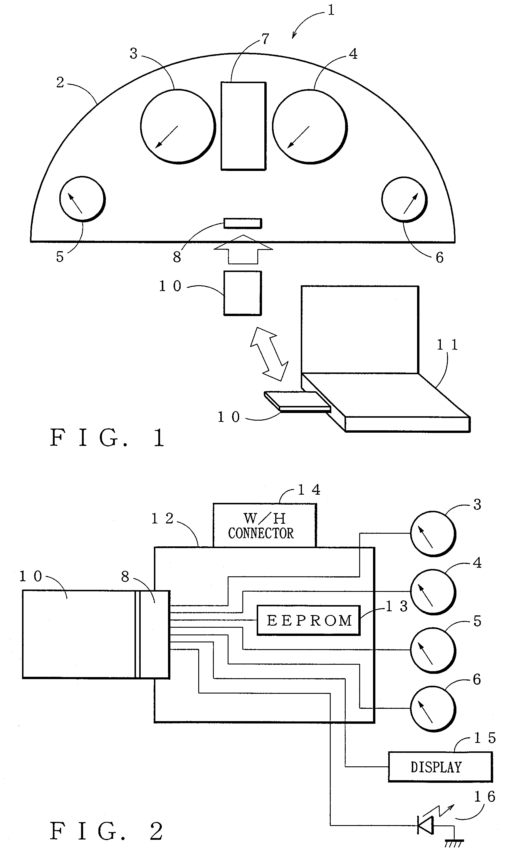
[0072]FIG. 1 is a general constitutional view showing a vehicle-mounted meter system according to the present invention. A vehicle-mounted meter system 1 according to the present invention has a combination meter main body (meter unit) 2. In a front side of the combination meter unit 2, there are arranged a plurality of meters and a display 7 of LED (liquid crystal display) or the like. The meters includes a vehicle speed meter 3, a tachometer 4 indicating an engine revolution speed, and a fuel meter 5 indicating a remaining quantity of a fuel like gasoline. Furthermore, in the front side of the combination meter unit 2, a connector 8 is provided under the display 7 for detachable connection with a control unit 10.

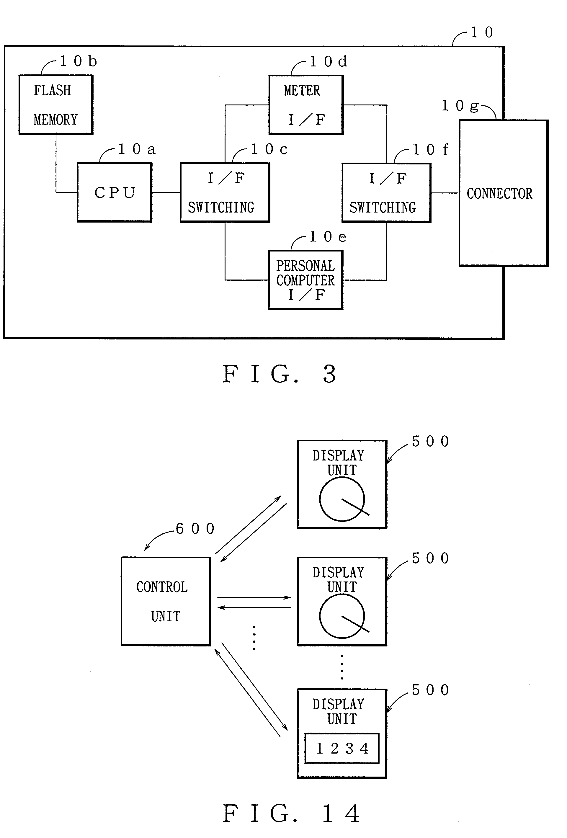
[0073]The control unit 10 is a card type one such as a PC card of an ATA standard. The PC card complies with a PC card standard a...


PUM


Abstract

A vehicle-mounted meter system includes: an inputting and outputting circuit for data measured to show a condition of the vehicle, a control circuit for controlling the system as a whole and for procession of the data, a meter main body, and a control unit detachably attached to the meter main body. The data inputting and outputting circuit is arranged on the meter main body, and the control circuit is arranged on the control unit. Preferably, the meter main body has a random bus structure corresponding to the data inputting and outputting circuit, and the bus structure has a buffer through which communication is allowed between the data inputting and outputting circuit and the control circuit.

Description

BACKGROUND OF THE INVENTION[0001]1. Field of the Invention[0002]The present invention relates to a meter system applicable to meters mounted in an automotive vehicle.[0003]2. Background Art[0004]A conventional vehicle-mounted meter is disclosed in Japanese Patent Application Laid-open No. 2003-194595. FIG. 8 is an exploded perspective view showing a construction of the conventional meter. The meter has a dial plate 101, a light guiding plate 102, a bearing plate 103, a fore cover 104, a circuit board 105, and a rear cover 106. The dial plate 101 is elongated in a transverse direction to comply with a combination meter including meters for vehicle speed, engine revolution speed, fuel quantity, and cooling water temperature, etc. The dial plate 101 is provided with a meter scale pattern 111a for vehicle speed, engine revolution speed, fuel quantity, and cooling water temperature, a winker indication pattern 111b, a warning indication pattern 111c, etc. The meter pattern 111a is provid...

Claims


Application Information

Patent Timeline
Patent Type & Authority Patents(United States)
IPC IPC(8): G06F3/00G05B23/00B60K35/00G08C19/00B60K37/02B60R16/02G06F7/00G08C17/00G08C23/04
CPCB60K37/02
Inventor KONDO, KAZUAKIASHIZAWA, SHOZO
Owner YAZAKI CORP
Why Eureka
Try Eureka