
Methods of and apparatus for pressure-ram-forming metal containers and the like

a technology of metal containers and pressure rams, which is applied in the direction of transportation and packaging, rigid containers, other domestic articles, etc., can solve the problems that conventional can-producing operations, however, cannot achieve such configurations, and achieve the effects of reducing the deleterious effects of damage, reducing the damage, and increasing the hydrostatic pressur

Inactive Publication Date: 2006-09-19
MONTEBLLO PACKAGING A DIV OF GREAT PACIFIC ENTERPRISE INC
View PDF24 Cites 45 Cited by
  • Summary
  • Abstract
  • Description
  • Claims
  • Application Information

AI Technical Summary

Benefits of technology

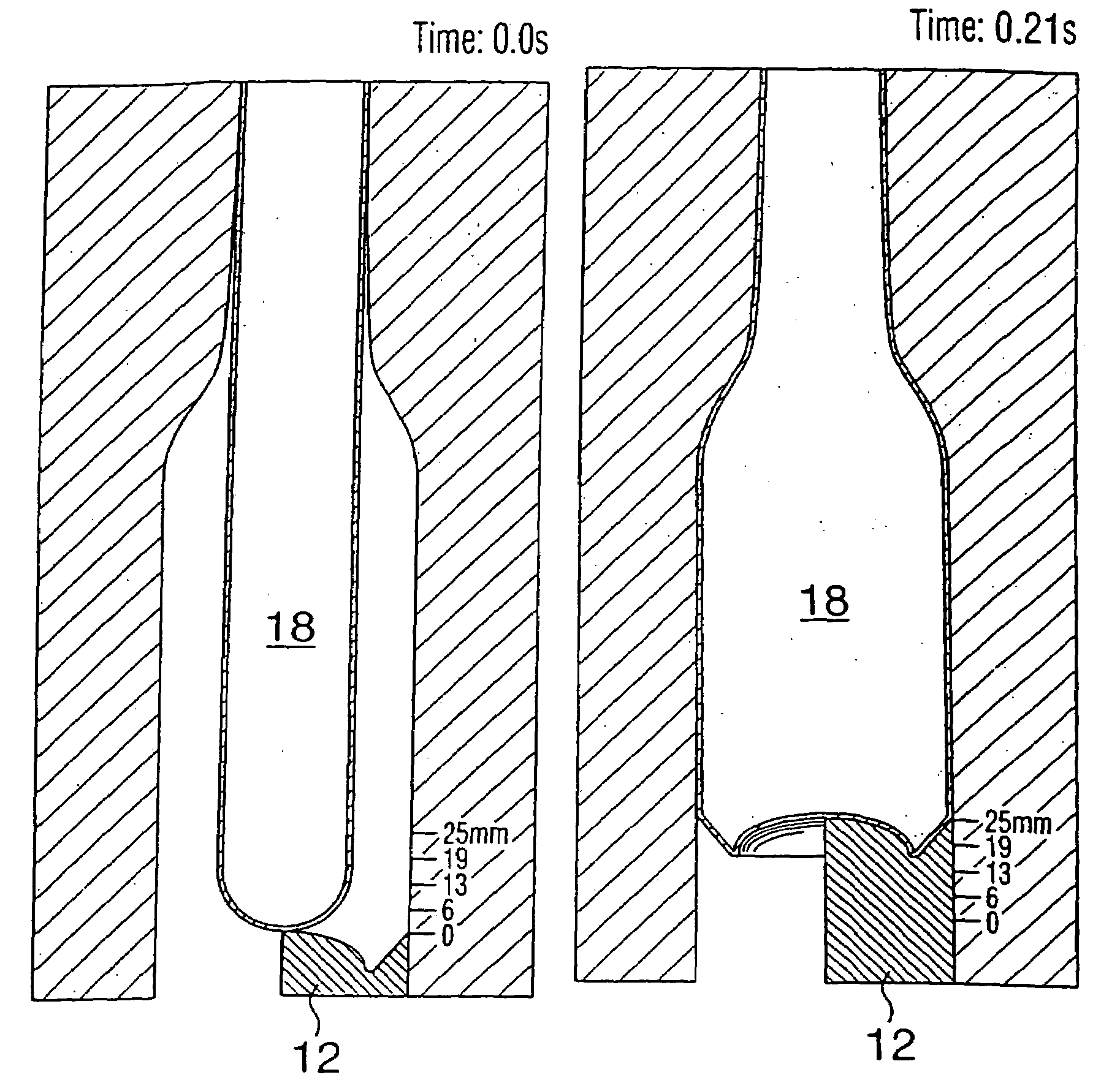
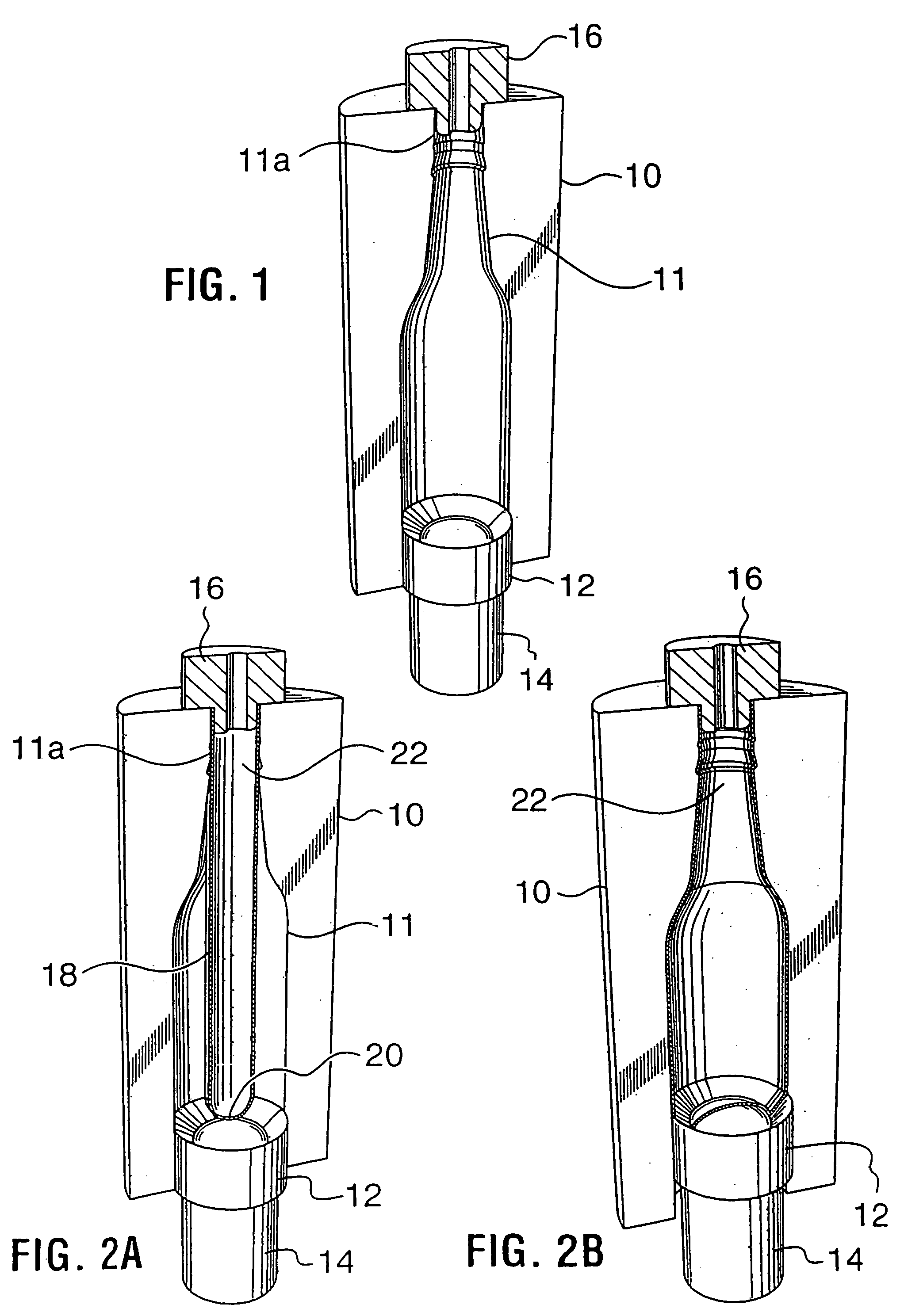
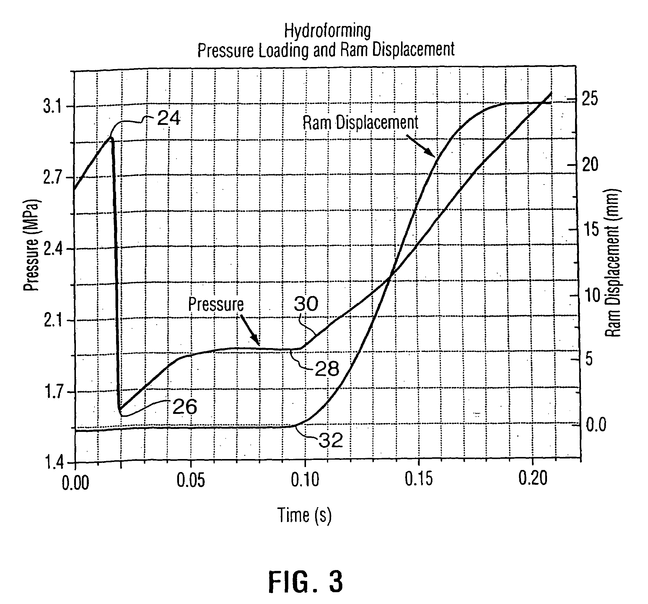
[0016]Also in accordance with the invention, the step of subjecting the preform to internal fluid pressure comprises simultaneously applying internal positive fluid pressure and external positive fluid pressure to the preform in the cavity, the internal positive fluid pressure being higher than the external positive fluid pressure. The internal and external pressure are respectively provided by two independently controllable pressure systems. Strain rate in the preform is controlled by independently controlling the internal and external positive fluid pressures to which the preform is simultaneously subjected for varying the differential between the internal positive fluid pressure and the external positive fluid pressure. In this way, more precise control of the strain rates may be achieved. In addition, the increased hydrostatic pressure may reduce deleterious effects of damage (voids) associated with the microstructure of the material.

Problems solved by technology

Conventional can-producing operations, however, do not achieve such configurations.

Method used


Image

  • Methods of and apparatus for pressure-ram-forming metal containers and the like
  • Methods of and apparatus for pressure-ram-forming metal containers and the like
  • Methods of and apparatus for pressure-ram-forming metal containers and the like

Examples


second embodiment

[0050]the method of the invention is illustrated in FIGS. 4A–4D. In this embodiment, as in that of FIGS. 2A and 2B, the cylindrical preform 38 has an initial outside diameter equal to the minimum diameter (neck) of the final product. However, in this embodiment it is assumed that the forming strains of the PRF operation exceed the formability limits of the preform. In this case, two sequential pressure forming operations are required. The first (FIGS. 4A and 4B) does not require a ram and simply expands the preform within a simple split die 40 to a larger diameter workpiece 38a by internal pressurization. The second is a PRF procedure (FIGS. 4C and 4D), starts with the workpiece as initially expanded in the die 40 and, employing a split die 42 with a bottle-shaped cavity 44 and a punch 46 driven by a ram 48, i.e., using both internal pressure and the motion of the ram, produces the final desired bottle shape, including all features of the side-wall profile and the contours of the bo...

third embodiment

[0051]A third embodiment is shown in FIGS. 5A and 5B. In this embodiment, the preform 50 is made with an initial outside diameter that is greater than the desired minimum outside diameter (usually the neck diameter) of the final bottle-shaped container. This choice of preform may result from considerations of the forming limits of the pre-forming operation or may be chosen to reduce the strains in the PRF operation. In consequence, manufacture of the final product must include both diametrical expansion and compression of the preform and thus can not be accomplished with the PRF apparatus alone. A single PRF operation (FIG. 5A, employing split die 52 and ram-driven punch 54) is used to form the wall and bottom profiles (as in the embodiment of FIGS. 2A and 2B) and a spin forming or other necking operation is required to shape the neck of the container. As illustrated in FIG. 5B, one type of spin forming procedure that may be employed is that set forth in U.S. Pat. No. 6,442,988, the...


PUM

PropertyMeasurementUnit
temperatureaaaaaaaaaa
displacementaaaaaaaaaa

Abstract

A method of forming a bottle-shaped or other contoured metal container by subjecting a hollow metal preform having a closed end to internal fluid pressure to cause the preform to expand against the wall of a die cavity defining the desired shape, and advancing a punch by means of a backing ram into the die cavity to displace and deform the closed end of the preform either before or after expansion begins but before it is complete. The pressure-subjecting step is performed by simultaneously subjecting the preform in the die cavity to independently controllable internal and external positive fluid pressures and varying the difference between them to control strain rate. Apparatus for performing the method includes a split die with plural split inserts disposed in tandem to define the die cavity wall and heaters respectively inserted within the preform and arranged to heat the backing ram.

Description

CROSS REFERENCE TO RELATED APPLICATIONS[0001]This application is a continuation of U.S. patent application Ser. No. 10 / 284,912, filed Oct. 31, 2002, now U.S. Pat. No. 6,802,196, which is a continuation-in-part of U.S. patent application Ser. No. 10 / 007,263, filed Nov. 8, 2001 (now abandoned), and of international application No. PCT / CA 02 / 00644 filed May 1, 2002, designating the United States, which is also a continuation-in-part of the aforesaid U.S. patent application Ser. No. 10 / 007,263 (now abandoned), which is a continuation-in-part of U.S. patent application Ser. No. 09 / 846,546, filed May 1, 2001 (now abandoned), the entire disclosure of each of which is incorporated herein by this reference.BACKGROUND OF THE INVENTION[0002]This invention relates to methods of and apparatus for forming metal containers or the like, utilizing internal fluid pressure to expand a hollow metal preform or workpiece against a die cavity. In an important specific aspect, the invention is directed to ...

Claims


Application Information

Patent Timeline
Patent Type & Authority Patents(United States)
IPC IPC(8): B21D26/02B65D1/00B21D22/14B21D22/16B21D26/049B21D51/10B21D51/16B21D51/26
CPCB21D22/16B21D26/033B21D26/041B21D26/049B21D51/16B21D26/047Y10T29/49805
Inventor GONG, KEVINHAMSTRA, PETERMACEWEN, STUARTMALLORY, ROBERTMOULTON, JAMES D.
Owner MONTEBLLO PACKAGING A DIV OF GREAT PACIFIC ENTERPRISE INC
Learn More