Damper mechanism for a lockup clutch

a technology of lockup clutch and hysteresis torque, which is applied in the direction of fluid couplings, rotary clutches, gearing, etc., can solve the problems of reducing the lifetime of the elastic member, increasing the hysteresis torque and wear on the elastic member, etc., and achieves the suppression of the increase in hysteresis torque and wear, prolonging the shape, and increasing the lifetime

Active Publication Date: 2006-09-19
EXEDY CORP
View PDF19 Cites 9 Cited by
  • Summary
  • Abstract
  • Description
  • Claims
  • Application Information

AI Technical Summary

Benefits of technology

[0012]With the damper mechanism for the lockup device described above, the radial ends on the circumferentially opposite ends of each of the first and second windows are inclined with respect to a straight line which extends through the center of the damper mechanism and the circumferential center of the first or second window, and will be referred to as a “center line” hereinafter. The angle θ between this center line and the radial ends is 0.05 to 0.60 times as large as the maximum torsion angle θ m, which is the torsion angle defined between the first and second rotary members when the first and second windows compress the elastic members to the maximum extent. Because the angle θ is in the foregoing range with respect to θ m, the force that pushes the elastic members radially outward can be suppressed, and an increase in the amount of compression of the radially outer portion of the elastic members can be suppressed. This can extend the lifetime of the elastic members.
[0014]With this damper mechanism for a lockup device, because the angle θ is in the aforementioned range with respect to the angle θ m, the force that pushes the elastic members radially outward can be suppressed, and an increase in the amount of compression of the radially outer portion of the elastic members can be suppressed. This can extend the lifetime of the elastic members.
[0016]With this damper mechanism for a lockup device, because the angle θ is in the aforementioned range with respect to the angle θ m, the force that pushes the elastic members radially outward can be suppressed, and an increase in the amount of compression of the radially outer portion of the elastic members can be suppressed. This can extend the lifetime of the elastic members.
[0018]With this damper mechanism for a lockup device, the coil spring has a relatively elongated shape. This type of coil spring is liable to be deformed by a force acting perpendicular to a longitudinal direction of the coil. Therefore, the elastic members are vulnerable to a radially outward force. However, because the angle θ of the radial ends of the first and second windows is appropriately set with respect to the angle θ m, an increase in hysteresis torque and wear can be suppressed even in a structure employing elastic members formed of relatively long coil springs.
[0019]According to the damper mechanism for a lockup device of the present invention, elastic members can have an increased lifetime by appropriately setting the size of the angle θ with respect to the angle θ m.

Problems solved by technology

This reduces the lifetime of the elastic members.
This causes contact between the elastic members and the window ends, and thus increases hysteresis torque and wear on the elastic members.

Method used


Image

  • Damper mechanism for a lockup clutch
  • Damper mechanism for a lockup clutch
  • Damper mechanism for a lockup clutch

Examples


Embodiment Construction

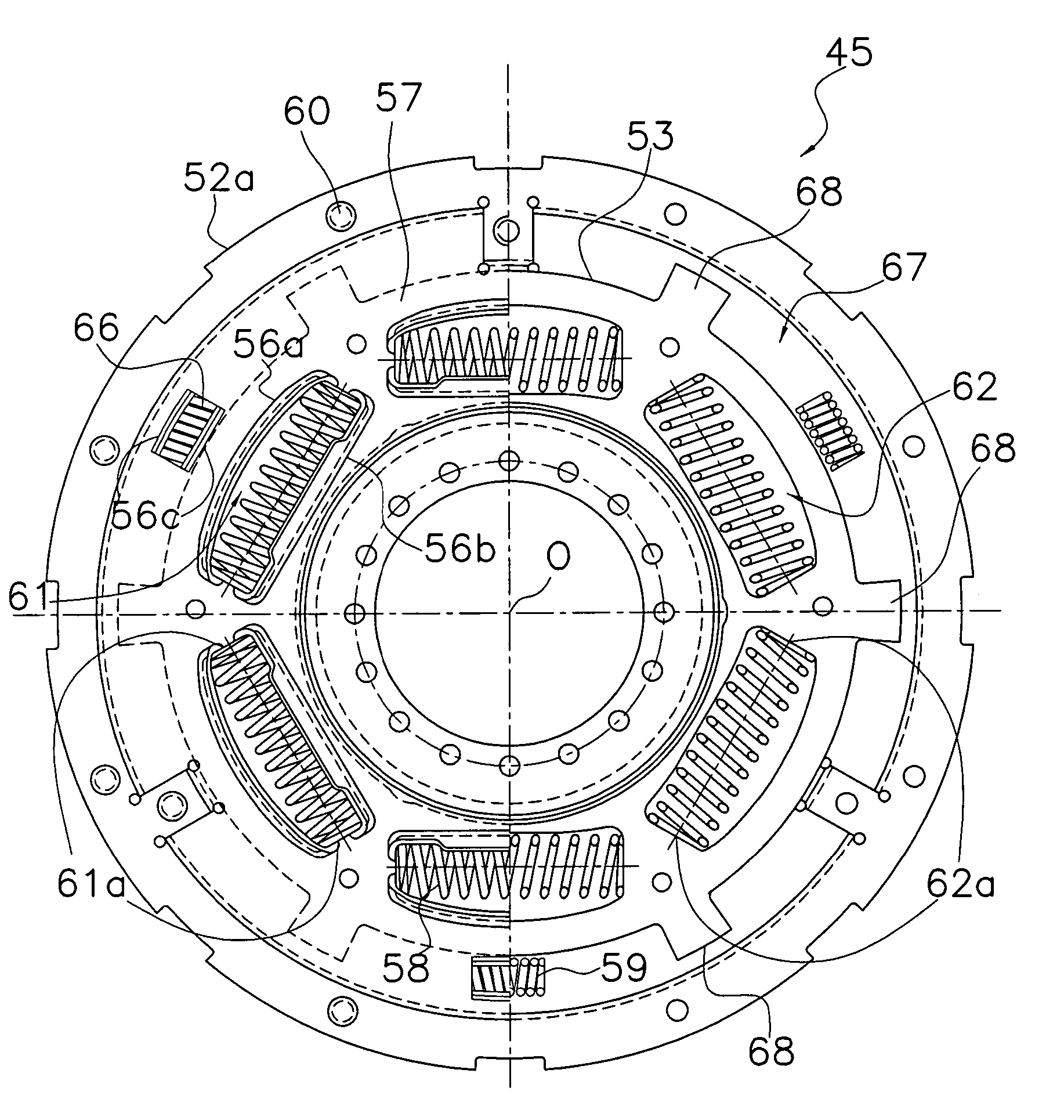
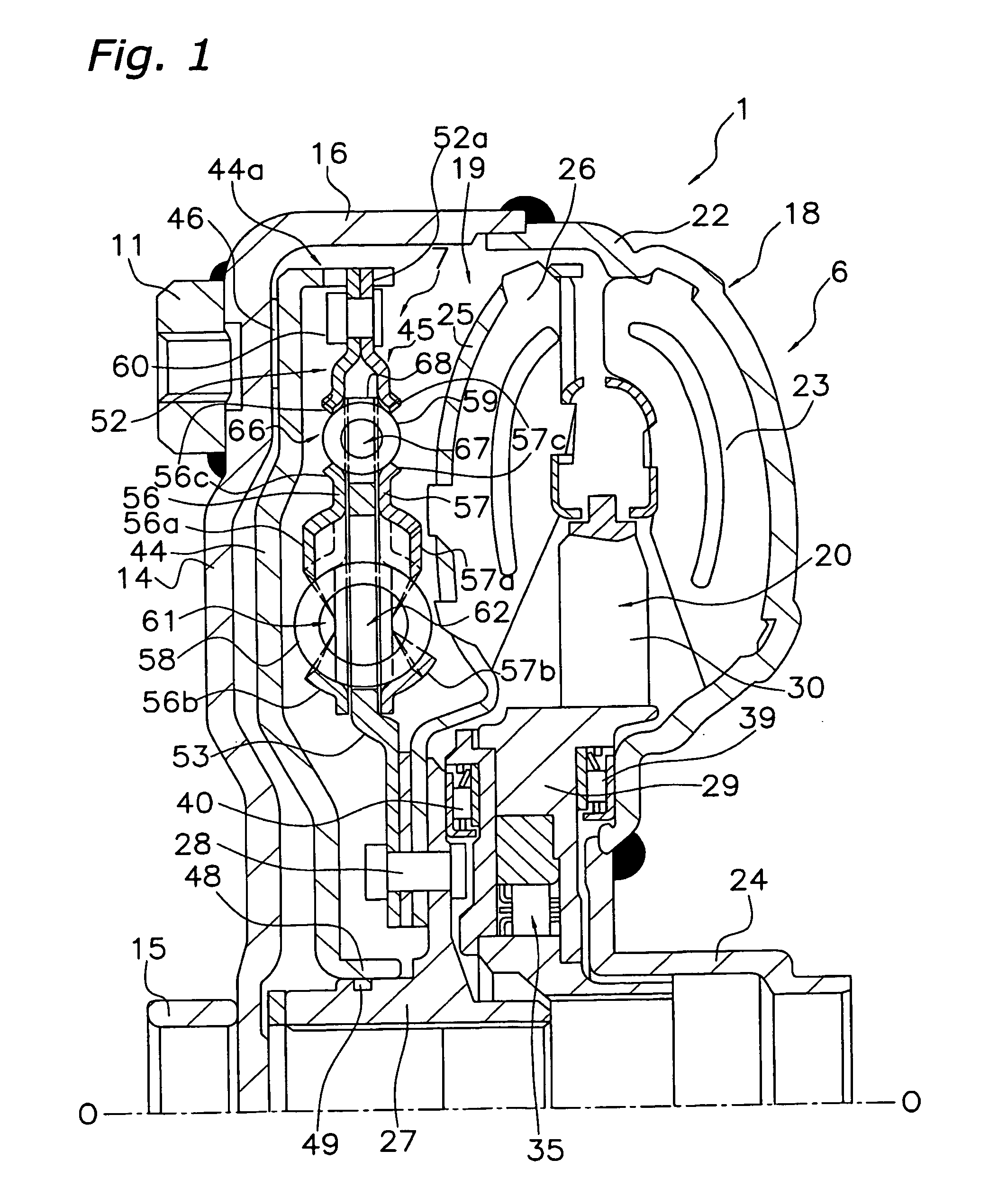
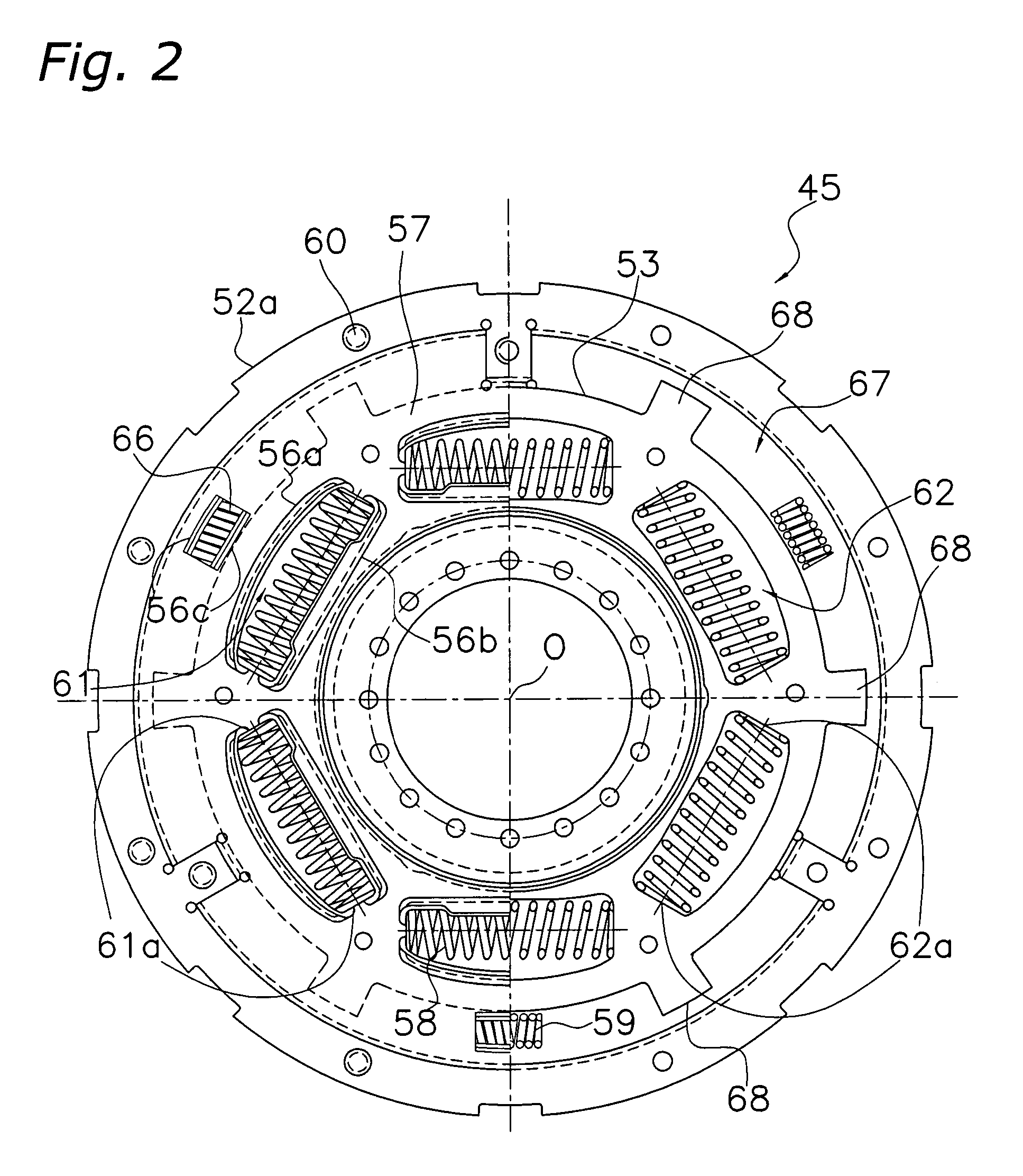
[0027]1. Structure of the Torque Converter

[0028]FIG. 1 shows a schematic cross section of a torque converter 1 employing an embodiment of the present invention. The torque converter 1 is a device for transmitting torque from a crankshaft (not shown) of an engine to an input shaft (not shown) of a transmission. Although not shown, the engine is arranged on the left side of FIG. 1, and the transmission is arranged on the right side of FIG. 1. In FIG. 1, O—O represents a rotation axis of the torque converter 1.

[0029]The torque converter 1 primarily includes a torus 6 which is formed of three kinds of vane wheels (i.e., an impeller 18, a turbine 19 and a stator 20), and a lockup device 7.

[0030]A front cover 14 is a circular disk-like member, and is arranged near the end of the crankshaft of the engine. A center boss 15 is welded to a radially inner portion of the front cover 14. A plurality of nuts 11, which are equally spaced from each other in the rotational direction (i.e., the circu...


PUM


Abstract

A damper mechanism for a lockup device 7 is a device for mechanically transmitting a torque in a torque converter 1. A coil spring 58 is arranged in first and second windows 61 and 62 overlapping with each other, and is compressed in accordance with the relative rotation of drive and driven members 52 and 53. A maximum torsion angle θ m is defined when the coil springs 58 are compressed to a maximum extent by relative rotation between the drive and driven members 52 and 53. Each of the first and second windows 61 and 62 has an outer periphery longer than an inner periphery. Each ends 61a and 62a on the circumferential ends of the first and second windows 61 and 62 form an angle θ with respect to a center line extending through a center O of the damper mechanism and a circumferential center C1 or C2 of the first or second window 61 or 62, and this angle θ is in a range between 0.05 and 0.60 times as large as the maximum torsion angle θ m.

Description

BACKGROUND OF THE INVENTION[0001]1. Field of the Invention[0002]The present invention relates to a damper mechanism, and more particularly to a damper mechanism for a lockup device.[0003]2. Background Information[0004]A damper mechanism is used, for example, in a power transmission system for transmitting torque while absorbing and damping torsional vibrations. The damper mechanism includes a first rotary member, a second rotary member, and springs or elastic bodies, which will be generally referred to as “elastic members” hereinafter. These elastic members are arranged between the first and second rotary members, and are compressed when relative rotation occurs between these members. The springs may be formed of coil springs. The elastic bodies may be made of rubber or resin. The damper mechanism is employed in a clutch disk assembly, a flywheel assembly or a lockup device of a torque converter, as disclosed, for example, in Japanese Laid-Open Patent Publication No. H8-254246[0005]...

Claims


Application Information

Patent Timeline
Patent Type & Authority Patents(United States)
IPC IPC(8): F16H45/02F16F15/134F16F15/123
CPCF16F15/12313F16H45/02F16H2045/0294F16H2045/0231F16H2045/0226
Inventor MIZUKAMI, HIROSHI
Owner EXEDY CORP
Why Eureka
Try Eureka