Method and apparatus for reducing force transmitted from a base structure to a supported structure

a technology of supporting structure and reducing force, which is applied in the direction of mechanical equipment, machine supports, transportation and packaging, etc., can solve the problems of inability to provide the required isolation from shock and vibration, large, and expensive systems that need to be protected from damage, and achieves simple packaging, reduces transmission of force, and reduces the cost of tooling and per unit production cost of hdpe pallets.

Inactive Publication Date: 2006-09-19
GE MEDICAL SYST GLOBAL TECH CO LLC
View PDF12 Cites 36 Cited by
  • Summary
  • Abstract
  • Description
  • Claims
  • Application Information

AI Technical Summary

Benefits of technology

[0007]An embodiment of the present invention provides for a packaging system for reducing transmission of force from a base platform to a floating platform by employing a plurality of dampers mounted between the base platform and the floating platform. The dampers each comprise a single damping element having at least two contact arms affixed to either the base platform or the floating platform. A plurality of side panels attach to the base platform to enclose equipment that is mounted to the floating platform.
[0008]Apparatus is provided for reducing transmission of force from a base structure to a supported structure. The apparatus comprises a single damping element having at least two contact arms affixed to either the base structure or the supported structure. An affixing base plate is mounted between the damping element and the base structure and an affixing offset plate is mounted between the damping element and the supported structure. The single damping element provides resistance to force in multiple orthogonal spatial directions.
[0010]Certain embodiments of the present invention afford an approach to providing resistance to shock and vibration forces in multiple orthogonal spatial directions using simple dampers each having a single damping element. Certain embodiments also provide for a relatively simple packaging system that uses a plurality of the simple dampers in a simple configuration.

Problems solved by technology

Diagnostic medical systems, such as a diagnostic X-ray system having a large C-arm, are complex, large, heavy, and expensive systems that need to be protected from damage due to shock and vibration during shipment.
The two methods typically do not provide the required isolation from shock and vibration.
The tooling cost and per unit production cost of the HDPE pallet often prove to be prohibitive, however.
The methods and systems described above tend to be complex, expensive, and / or inadequate for reducing shock and vibration.

Method used


Image

  • Method and apparatus for reducing force transmitted from a base structure to a supported structure
  • Method and apparatus for reducing force transmitted from a base structure to a supported structure
  • Method and apparatus for reducing force transmitted from a base structure to a supported structure

Examples


Embodiment Construction

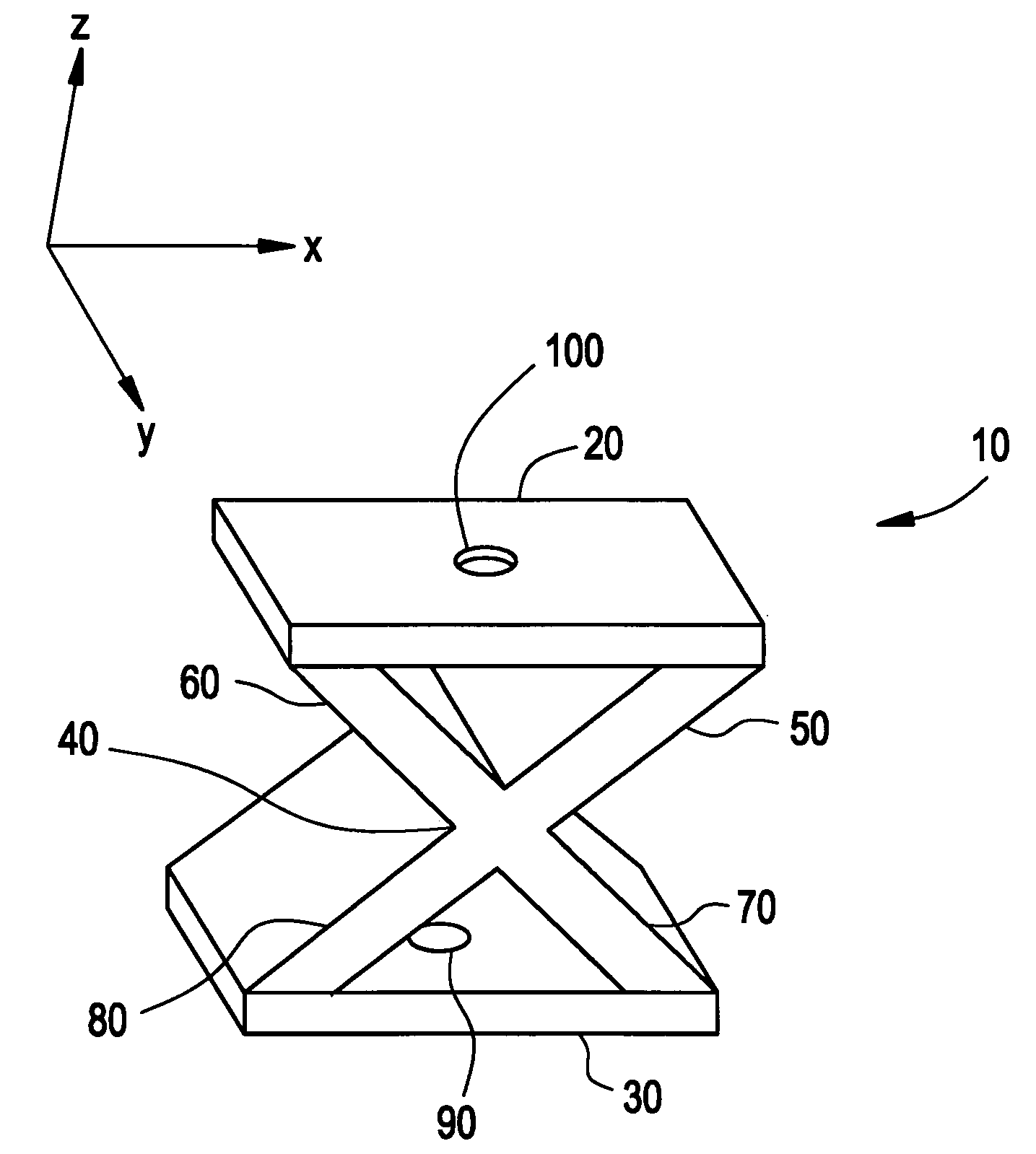
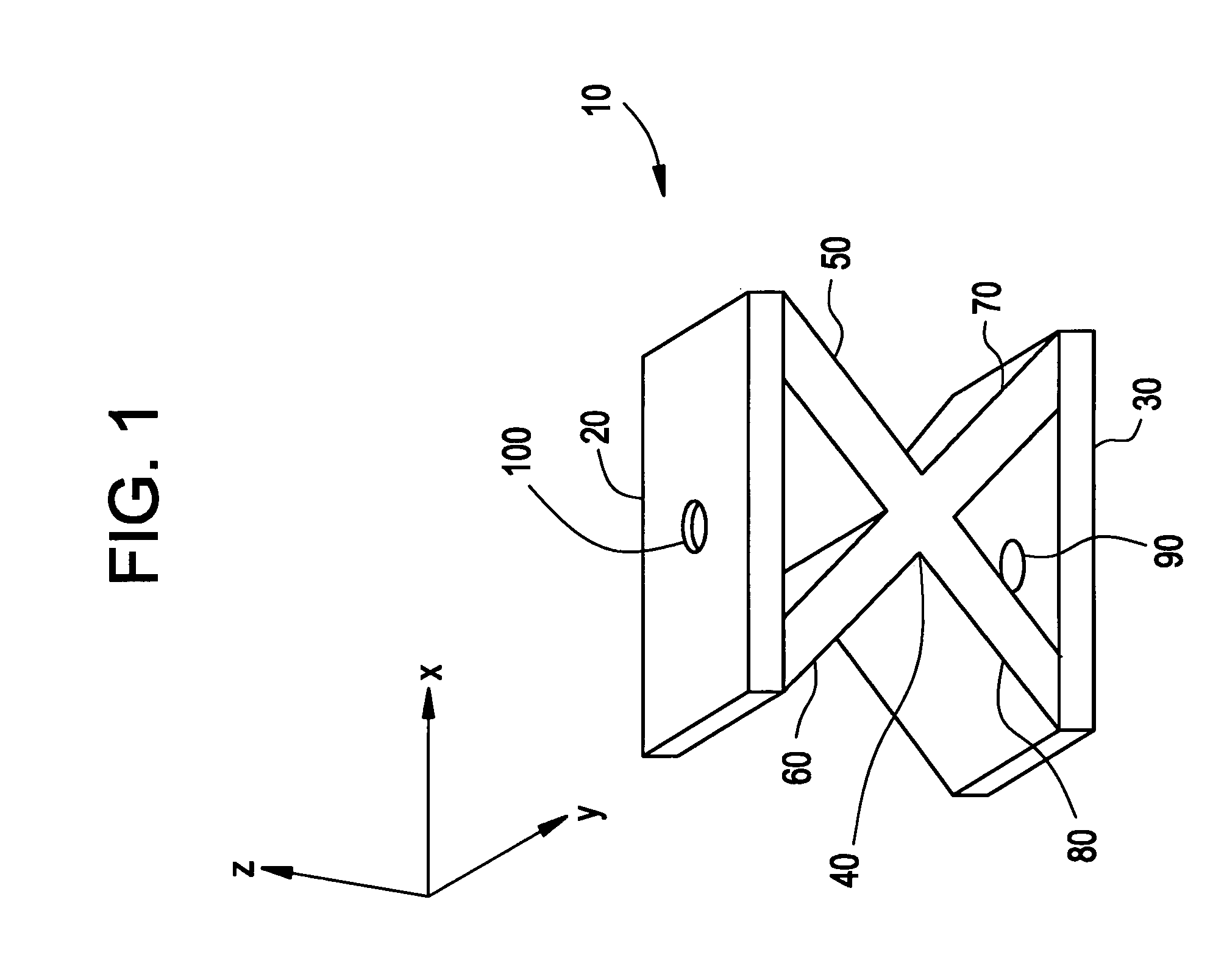
[0017]FIG. 1 is an isometric view of a damper 10 showing certain elements of the damper 10 in accordance with one embodiment of the present invention. The damper 10 comprises a base plate 30, an offset plate 20, and a single damping element 40. The single damping element 40 is a single molded piece of rubber having four contact arms 50, 60, 70, 80 forming a three-dimensional X shape in one embodiment of the present invention.

[0018]The two lower contact arms 70 and 80 connect to the base plate 30 and the two upper contact arms 50 and 60 connect to the offset plate 20. The base plate 30 and the offset plate 20 are made of steel in one embodiment of the present invention. A chemical bonding process may be used to bond the contact arms 50–80 of the rubber damping element 40 to the steel base plate 30 and steel offset plate 20.

[0019]The base plate 30 and the offset plate 20 each have a through-hole 90 and 100, respectively. The through-holes 90 and 100 may be used to bolt the damper 10 b...


PUM

PropertyMeasurementUnit
widthaaaaaaaaaa
widthaaaaaaaaaa
lengthaaaaaaaaaa

Abstract

A method and apparatus are disclosed for reducing transmission of force from a base structure to a supported structure. The method includes mounting a plurality of dampers between the base structure and the supported structure. Each damper includes a single damping element having at least two contact arms affixed to either the base structure or the supported structure. Damping of forces is achieved by each damper in multiple orthogonal directions. The base structure is mounted to a transportation vehicle. The supported structure includes equipment mounted on a floating platform.

Description

BACKGROUND OF THE INVENTION[0001]Certain embodiments of the present invention relate to reducing forces transmitted from one structure to another. More particularly, certain embodiments of the present invention relate to reducing forces transmitted to a diagnostic medical system during shipment.[0002]Diagnostic medical systems, such as a diagnostic X-ray system having a large C-arm, are complex, large, heavy, and expensive systems that need to be protected from damage due to shock and vibration during shipment. Units are typically shipped all around the world in vehicles experiencing various road conditions.[0003]Various packaging systems and methods have been used in shipping medical systems. For example, one method includes mounting the medical system directly onto a wooden base with the chassis of the system elevated and supported on wooden strips. Another method includes sandwiching expanded polyurethane (EP) foam between two layers of plywood and mounting the system on the top ...

Claims


Application Information

Patent Timeline
Patent Type & Authority Patents(United States)
IPC IPC(8): F16F3/02F16M1/00F16F1/373
CPCF16F1/373
Inventor JAYAKUMARAN, SUJAY
Owner GE MEDICAL SYST GLOBAL TECH CO LLC
Why Eureka
Try Eureka