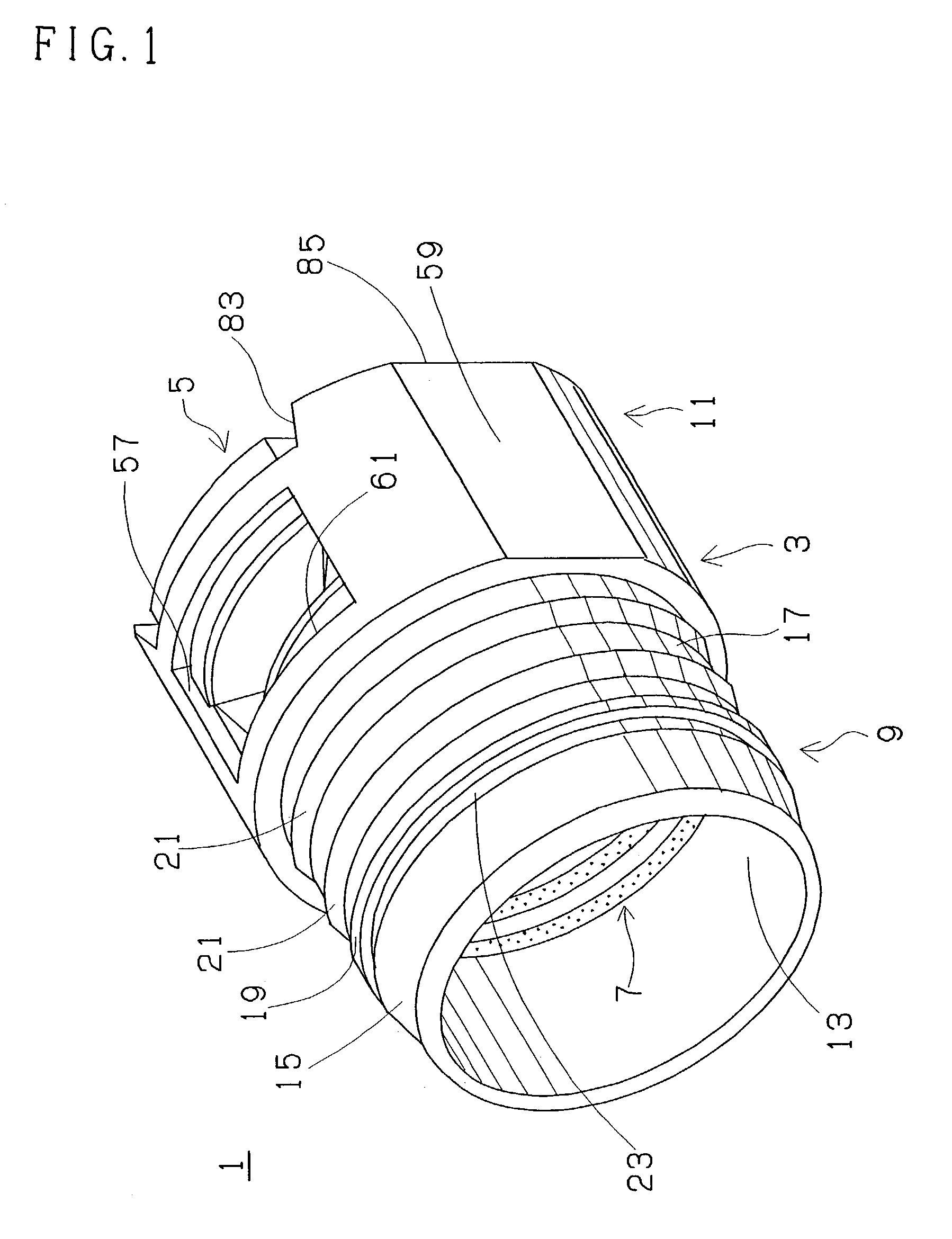
[0008]The quick connector has a tubular connector housing which is provided with a tube connecting portion on one axial end thereof and a projection receiving portion to receive the annular engagement projection of the pipe on an opposite axial end thereof. The quick connector also has
retainer means provided for the projection receiving portion and configured so as to snap-engage with the annular engagement projection of the pipe when the inserting end portion of the pipe is inserted into an
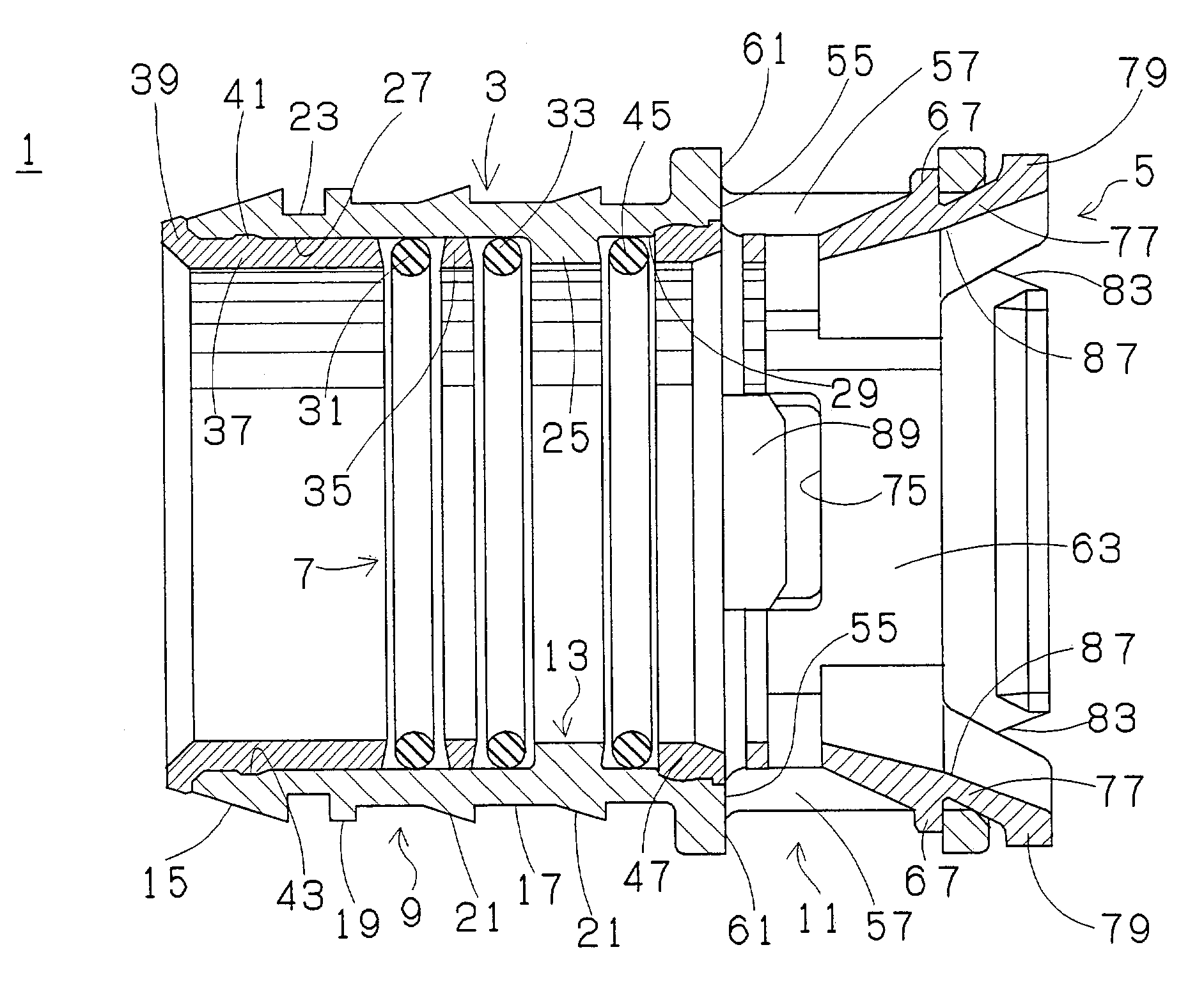
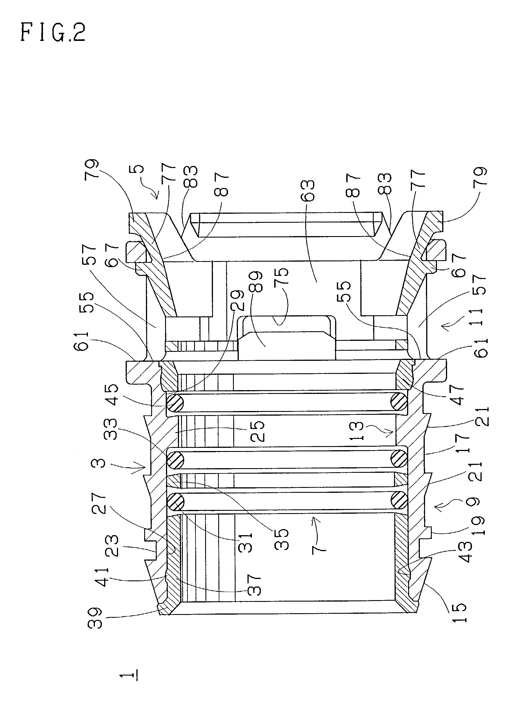
insertion opening on an end of the projection receiving portion. The quick connector further has sealing means disposed on one axial end of the projection receiving portion in the tubular connector housing, for example, on one axial end of an inside of the projection receiving portion in the tubular connector housing to provide a seal between the tubular connector housing and one axial end or end portion of the annular engagement projection of the inserting end portion provided on the pipe. The sealing means includes a first annular sealing member of
gasoline fuel resistant property and a third annular sealing member of low-temperature resistant property located on an opposite axial end of the first annular sealing member in the tubular connector housing. The sealing means further includes a second annular sealing member for waterproofness and dust proofness located on an opposite axial end of the third annular sealing member in the tubular connector housing. The second annular sealing member has waterproof and dust proof functions with respect to the third annular sealing member. That is, the second annular sealing member prevents water and dust from penetrating into an end of the third annular sealing member. Therefore, deterioration of the third annular sealing member is prevented and thereby the sealing means is improved in low-temperature resistant property.
[0011]Specifically, the first annular sealing member may be made of
fluorine type rubber or of NBR type rubber of excellent gasoline resistant property, and the third annular sealing member may be made of
silicone type rubber, NBR type rubber,
ethylene-propylene-
diene terpolymer or flexible polyolefine type
thermoplastic resin. And, the second sealing member may be made of
fluorine type rubber, NBR type rubber,
silicone type rubber,
ethylene-propylene-
diene terpolymer or flexible polyolefine type
thermoplastic resin. More specifically, the first sealing member may be made of an elastic material of gasoline resistant property, selected from the group consisting of fluoro-rubber (FKM) and
acrylonitrile-butadiene rubber /
polyvinyl chloride blend rubber (NBR / PVC). The third annular sealing member may be made of an elastic material of low-temperature resistant property or low-temperature property, selected from the group consisting of fluoro-
silicone-rubber (FVMQ),
acrylonitrile-butadiene rubber (NBR), NBR / PVC,
ethylene-propylene-
diene-rubber (EPDM) and
thermoplastic olefin (TPO). And, the second annular sealing member may be made of NBR of excellent waterproof and dust proof properties, or of an elastic material of
ozone resistant property as well as waterproof and dust proof properties, selected from the group consisting of FKM, NBR / PVC, FVMQ, EPDM and TPO. Table 1 indicates properties of each material. FKM is relatively expensive and inferior in low-temperature resistant property, but is very excellent or superior in gasoline resistant property and
ozone resistant property, and therefore suitable for the first and the second annular sealing members. NBR / PVC has
ozone resistant property, and excellent gasoline resistant property although not so much as FKM. NBR / PVC further has excellent low-temperature resistant property although not so much as FVMQ, and is relatively low at cost. Therefore, NBR / PVC is suitable for the first to the second annular sealing members. Moreover, FVMQ is expensive, but has very excellent low-temperature resistant property and very excellent ozone resistant property, and therefore is suitable for the third and the second annular sealing members. On the other hand, NBR is relatively low in cost, and has excellent low-temperature resistant property although not so much as FVMQ, and further has waterproof and dust proof properties. So, NBR is suitable for the third and the second annular sealing members.
Fluorine type rubber, NBR / PVC, silicone type rubber, EPDM and TPO, which are all excellent in ozone resistant property, are suitable for the second annular sealing member as stated above.
[0014]A quick connector of the present invention is provided with an annular sealing member for waterproofness and dust proofness which is located on an opposite axial end of an annular sealing member of excellent or preferable gasoline resistant property, i.e., excellent or preferable
gasoline fuel impermeability and / or swelling resistant property and an annular sealing member of low-temperature resistant property. Consequently, the quick connector of the present invention is high in gasoline resistant property and, in addition, keeps preferable low-temperature resistant property constantly.

