
Multi-stage abrasive-liquid jet cutting head

Inactive Publication Date: 2006-09-19
UNITED MATERIALS INT +1
View PDF12 Cites 25 Cited by
  • Summary
  • Abstract
  • Description
  • Claims
  • Application Information

AI Technical Summary

Benefits of technology

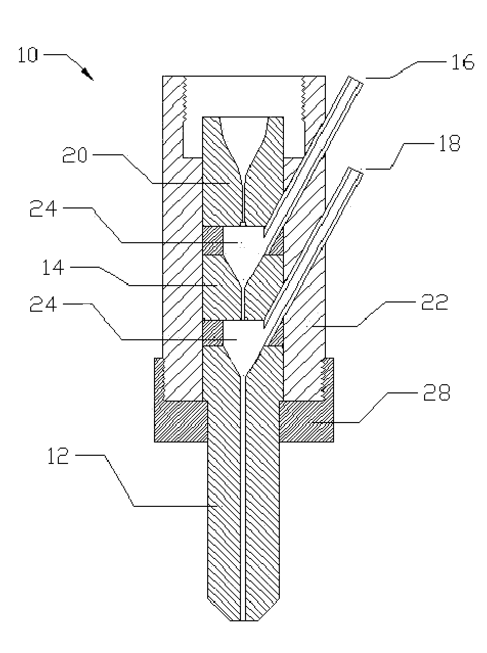
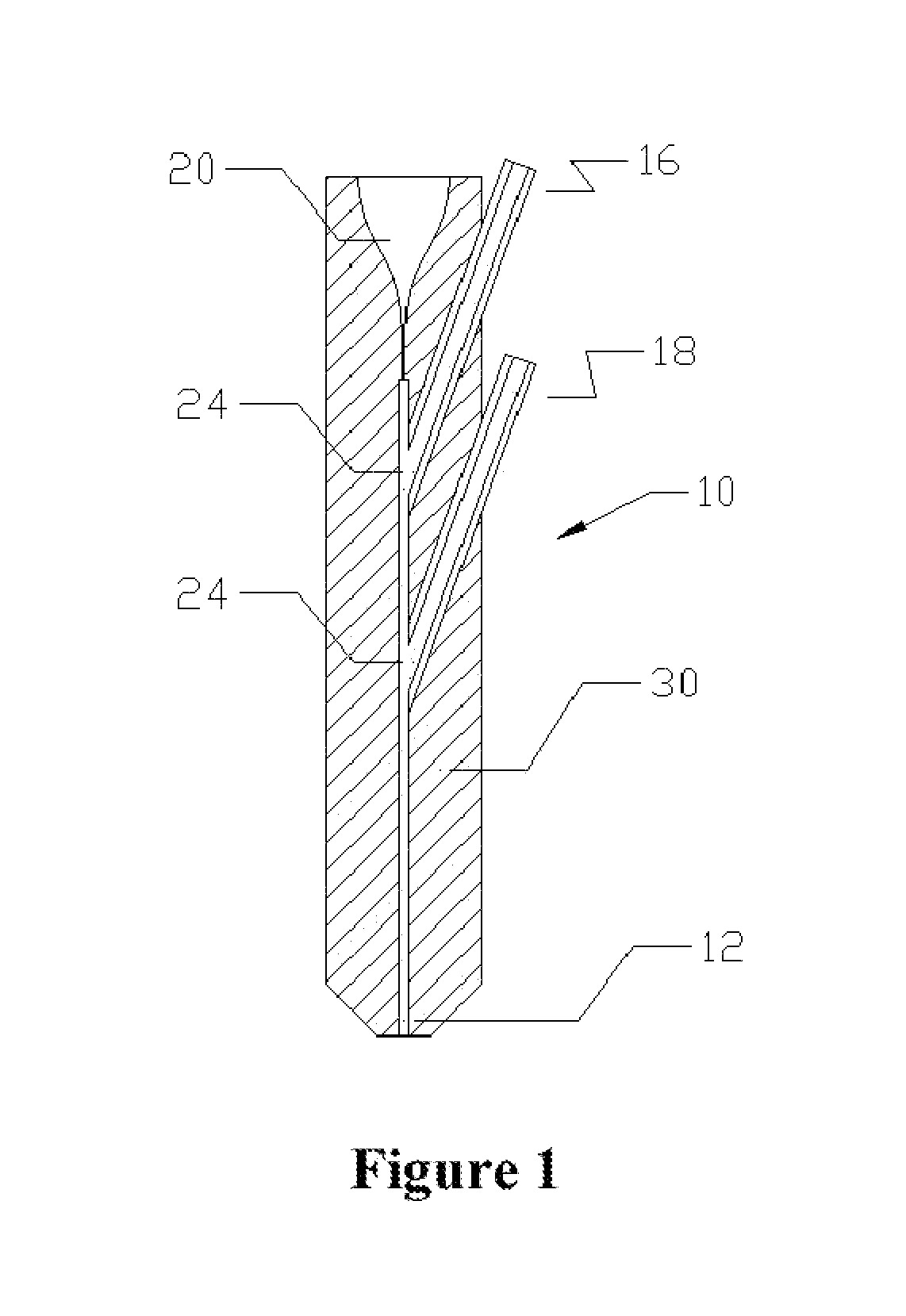
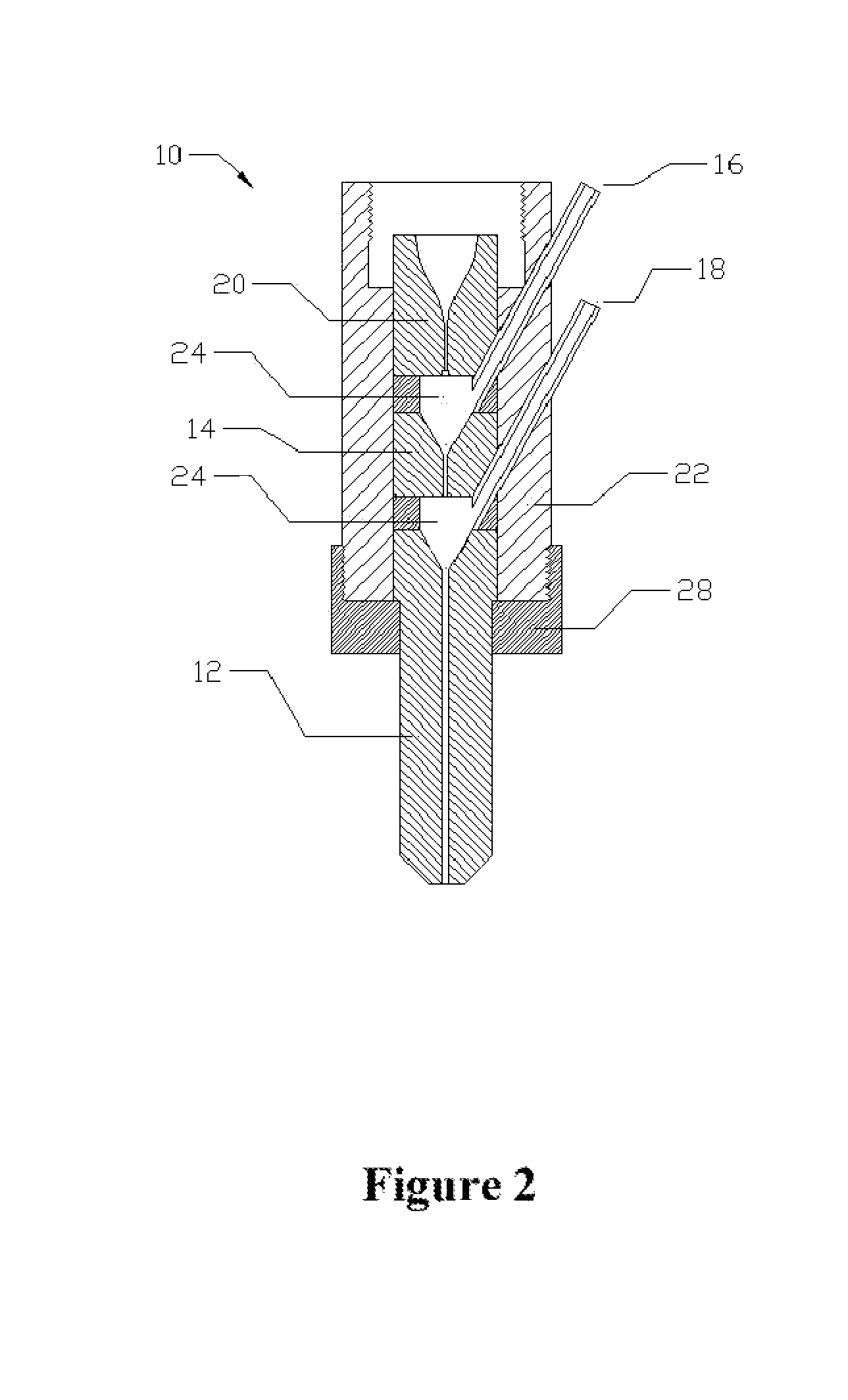
[0018]Two or more feeding tubes are used to introduce abrasive into the waterjet stream in order to create more impact energy for faster cutting rates of subject materials. Improvements and novel techniques for high-pressure abrasive-liquid jet technology are disclosed herein describing more efficient use of energy and resources compared to current abrasive jet technology to allow for faster abrasive jet cutting rates of subject materials. These benefits are realized through the following improvements: use of two or more specially engineered abrasive particles with specific properties and use of these mixed particles in the abrasive jet stream; optimization of individual components of the cutting head and optimization of their relationships to each other as a complete system.
[0019]It is a general object of the present invention to provide a multistage water jet cutting head using non-conventional abrasives and optimized cutting head configurations both designed for improvements to traditional abrasive jet applications along with creating new areas of technology currently not associated with abrasive jet.
[0020]Another object of the present invention is to provide a multistage water jet cutting head using subject materials that are processed more efficiently through optimization of the abrasive mixture process into a water jet stream, resulting with reduced overall costs of the abrasive jet technique for cutting or other material removing technology.
[0021]Yet another object of the present invention is to provide a multistage water jet cutting head that provides improvements to the abrasive jet technique generating increased cutting speeds through achieving better tolerances, and higher resulting surface finish quality of subject materials.
[0022]Still another object of the present invention is to provide a multistage water jet cutting head that fosters the creation of several novel manufacturing technologies based on the abrasive jet technique as disclosed herein.
[0023]A further object of the present invention is to provide a multistage water jet cutting head where a multi-stage approach allows for a more gradual, and more effective, mixing of the abrasive particles with the waterjet to allow for faster particle acceleration and greater cutting speeds.

Problems solved by technology

Conventional abrasivejet technology is used to cut a variety of materials but is found to be highly inefficient in the use of energy and resources mainly due to equipment design limitations that incorporate use of garnet as the abrasive.
Conventional abrasivejet is also currently limited to perform one purpose at a time such as thru cutting of material or surface removal of material as there are not any abrasivejet systems currently producing useful byproducts simultaneously with the initial purpose of material removal.
A more important similarity, as well as deficiency, of conventional abrasivejet technology is the widespread use of garnet abrasives over all other abrasives.
Conventional abrasivejet technology does not effectively use abrasives other than garnet due to numerous factors such as higher initial costs of most other hard abrasives compared to garnet and the inability of other hard abrasives to cut significantly faster than garnet.
These factors generally result in higher overall costs of abrasive consumption after considering the final amount of material cut.
There is also the limitation of conventional abrasivejet cutting head technology preventing use of harder abrasives than garnet because of the increased costs of accelerated nozzle wear created by these harder abrasives.
The similarities of conventional cutting head designs' primary use of only one type of nozzle material, use of only one abrasive medium, and use of only two types of orifice materials, mainly produce a common limitation of an approximate 3:1 nozzle to orifice ratio.
Therefore, a relatively larger volume of area of area in the nozzle bore compared to the smaller area of volume of the liquid energy creates inefficiencies.
A solution to create a more efficient use of energy would incorporate a smaller nozzle to orifice ratio such as 2:1 but this solution is not currently viable with use of conventional cutting heads and garnet abrasives.
The best solution for conventional technology has been use of relatively small volumes of high-pressure liquid in the abrasivejet mixture allowing for variable cutting, but this also reduces the effective cutting energy by being dispersed over a greater area, hence, the effective energy is not optimally focused.
A ring orifice plate or disk such as employed in the U.S. Pat. Nos. 3,424,386, 4,080,762 and 4,125,969 to provide the fluid jets around the sand stream has many disadvantages including: the introduction of pressurized fluid tangentially into a nozzle a short distance above the orifice disk is not conducive to the generator of a coherent fluid jet due to flow disturbances upstream of the orifices; sand in the central portion of a nozzle creates an abrasive environment that can weaken the interior wall of the annular fluid chamber without being detected; pressurized fluid in the outer annular space results in a nozzle that is very large in dimensions as both interior and exterior walls must be sized to accommodate the fluid pressure; and sealing the annular orifice disk can be very troublesome.
These problems would be intensified at higher pressures.
The problem areas with the prior art cutting head shown in this patent are the orifice, the mixing chamber and the liquid jet.
A problem with this design is the separation effect of the jet as it starts to break up.
This methods adds abrasive to the stream before entering the orifice.
The advantage of this method is that it produces a coherent jet, but the disadvantage is that components such as tubing, valves and orifices wear out quickly due to the abrasive suspension inside the system severely eroding everything it contacts.
Another disadvantage of the orifice designs in conventional abrasivejet is the sharp transition from the pump tubing to the relatively small orifice.
This sharp transition creates a high resistance of the pressure flow and does not allow for property formed liquid optimization, resulting with jet distortion, and decrease in overall energy efficiency of the system.
However, there are many reasons why garnet is not the optimum abrasive available when considering the complete abrasivejet system, recycling and the ability to perform two or more processes in one operation.
One reason is that garnet is not the optimum abrasive is because it is not recyclable effectively.
Another disadvantage is that very hard subject materials such as carbides and hard ceramics are generally not cut with abrasivejet technology because of the very low cutting speed ability of garnet to cut these materials.

Method used


Image

  • Multi-stage abrasive-liquid jet cutting head
  • Multi-stage abrasive-liquid jet cutting head
  • Multi-stage abrasive-liquid jet cutting head

Examples


Embodiment Construction

[0030]At the outset, it should be clearly understood that like reference numerals are intended to identify the same structural elements, portions, or surfaces consistently throughout the several drawing figures, as may be further described or explained by the entire written specification of which this detailed description is an integral part. The drawings are intended to be read together with the specification and are to be construed as a portion of the entire “written description” of this invention as required by 35 U.S.C. §112.

[0031]For purposes of this patent, the terms appearing below in the description and the claims are intended to have the following meanings:

[0032]“Abrasive” means any particulate material intentionally introduced into a pressurized liquid jet in the form of sharp edge particles, such as angular, cubical, or non-spherical shapes, generally used for material removal or surface treatment upon interaction with subject material.

[0033]“Abrasivejet” means a mixture ...


PUM

PropertyMeasurementUnit
Fractionaaaaaaaaaa
Diameteraaaaaaaaaa
Concentrationaaaaaaaaaa

Abstract

A multistage abrasive-liquid jet cutting head comprising at least a first and a second mixing stage. Within the first mixing stage is a first mixing chamber arranged to accept a first flow of accelerated abrasive particles from a first abrasive feed tube and a pressurized liquid flow from an orifice and produce a pressurized slurry-like flow that is introduced to the second mixing stage. Within the second mixing stage is a second mixing chamber arranged to accept and mix is second flow of accelerated abrasive particles from a second abrasive feed tube with the pressurized slurry-like flow from the first mixing stage. An exit nozzle in fluid communication with the second mixing chamber that focuses the combination of the second flow of accelerated abrasive particles from the second abrasive feed tube with the pressurized slurry-like flow from the first mixing stage into an abrasive jet.

Description

[0001]This application claims priority of U.S. Provisional patent application to Benjamin F. Dorfman and Steven A. Rohring, Ser. No. 60 / 668,453 for METHODS FOR IMPROVING ABRASIVE JET TECHNOLOGY AND APPARATUS FOR THE SAME, filed on Apr. 5, 2005.FIELD OF INVENTION[0002]The invention relates to the field of high-pressure abrasive-liquid jet (also sometimes known as ‘Abrasive Waterjet’ or ‘Abrasivejet’) technology often used in material removal, and more specifically, improvements upon conventional abrasive-liquid jet technology in the area of multi-stage abrasive particle jet formation.BACKGROUND OF THE INVENTION[0003]Conventional abrasivejet technology is used to cut a variety of materials but is found to be highly inefficient in the use of energy and resources mainly due to equipment design limitations that incorporate use of garnet as the abrasive. Conventional abrasivejet is also currently limited to perform one purpose at a time such as thru cutting of material or surface removal ...

Claims


Application Information

Patent Timeline
IPC IPC(8): B24C5/04
CPCB24C1/045B24C7/0076B24C5/04Y10T83/0591Y10T83/364
Inventor DORFMAN, BENJAMIN F.ROHRING, STEVEN A.
Owner UNITED MATERIALS INT
Learn More