Reduced wear orthopaedic implant apparatus and method

a technology of orthopaedic implants and implants, which is applied in the field of joint prosthetic implants, can solve the problems of releasing debris in and around the surrounding tissue, reducing wear, and reducing wear, so as to reduce wear and reduce cross-shear

Inactive Publication Date: 2006-09-19
DEPUY PROD INC
View PDF45 Cites 69 Cited by
  • Summary
  • Abstract
  • Description
  • Claims
  • Application Information

AI Technical Summary

Benefits of technology

[0010]The present invention addresses the above needs, as well as others, by providing a prosthetic implant arrangement that includes multiple articulating surfaces that allow movement about different rotational axes. Each of the multiple articulating surfaces is restricted from full spherical pivotal motion, thereby reducing cross-shear, which has been found to reduce wear. Preferably, at least two articulating surfaces are provided, each allowing rotation about an orthogonal axis. With even two of such articulating surfaces, nearly all anatomical hip movements are possible.

Problems solved by technology

A set of problems associated with hip prosthesis arises from the wear of the hip implant bearings.
In particular, extensive use of a prosthetic hip can cause the bearings to wear, releasing debris in and around the surrounding tissue.
In such a prosthesis, it has been observed that the bearing surface of the UHMWPE liner wears, thereby producing particulate debris.
Particulate from UHMWPE wear can interfere with the motion capabilities of the prosthetic and furthermore can create an adverse biological reaction.
Similarly, if a metal liner is instead used, the wear from the metal on metal bearings (metal liner to metal femoral head) can release increased levels of metal ions in the body which can produce adverse health effects.
Ceramic liners do not produce metal ions, but are expensive and can fail in a brittle manner, which is highly undesirable.

Method used


Image

  • Reduced wear orthopaedic implant apparatus and method
  • Reduced wear orthopaedic implant apparatus and method
  • Reduced wear orthopaedic implant apparatus and method

Examples


Embodiment Construction

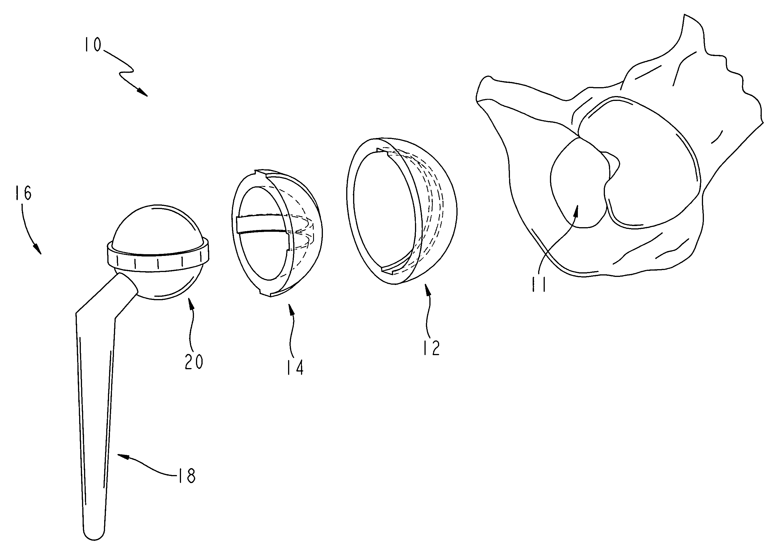
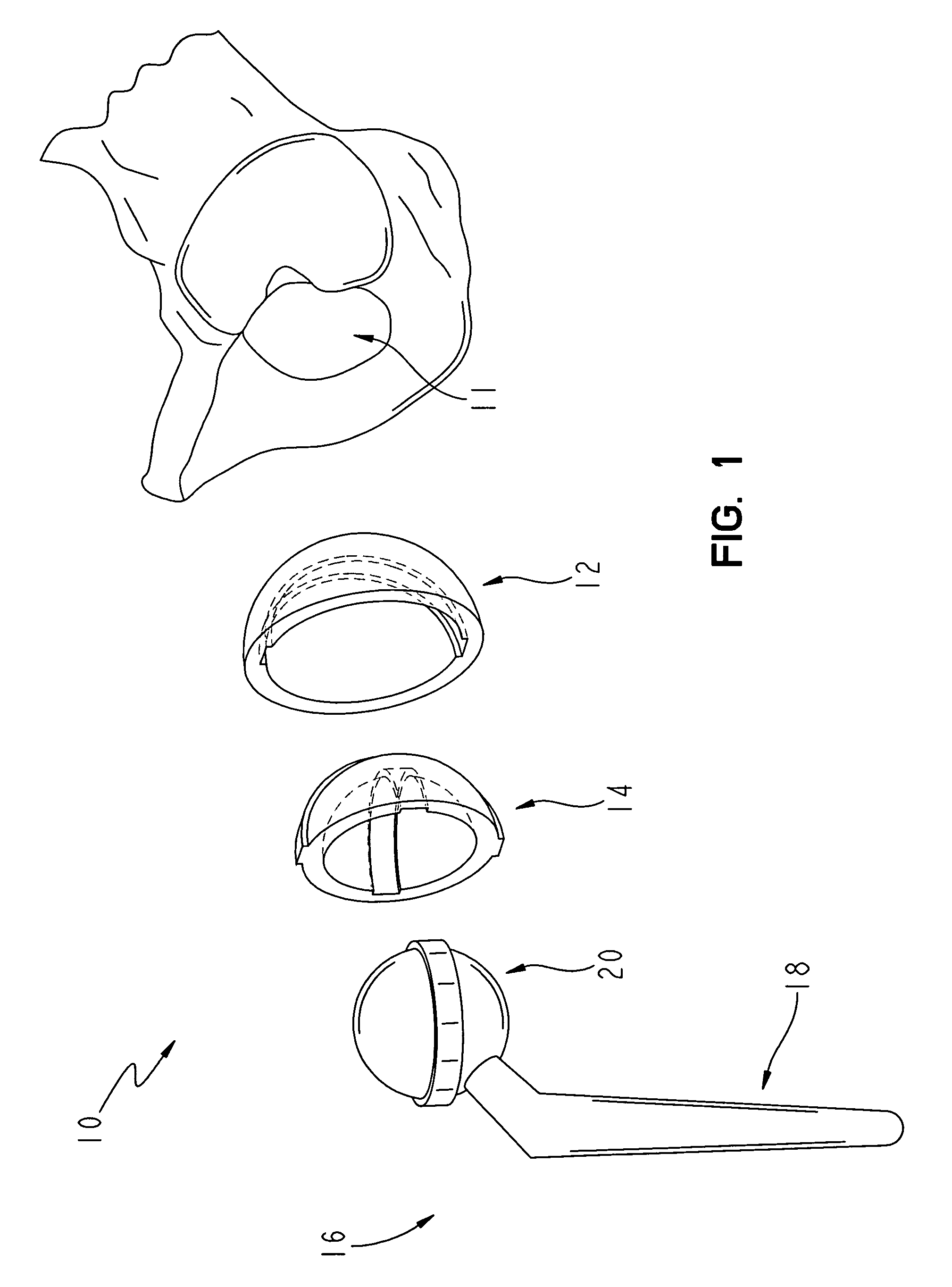
[0025]FIG. 1 shows an exploded perspective view of an exemplary hip implant arrangement 10 according to the present invention as well as a fragmentary bone structure showing an acetabulum 11 of a human patient The hip arrangement includes an acetabular shell 12, a liner 14 and a femoral component 16. The acetabular shell 12 is generally configured to be received in the acetabulum 11 of a patient, and the liner 14 is configured to be received in the acetabular shell 12. The femoral component 16 includes a femoral stem 18 and a femoral head 20. The femoral stem 18 is configured to be received into or at least supported by the femoral bone tissue of the patient, not shown, and the femoral head 20 is configured to be received in the liner 14.

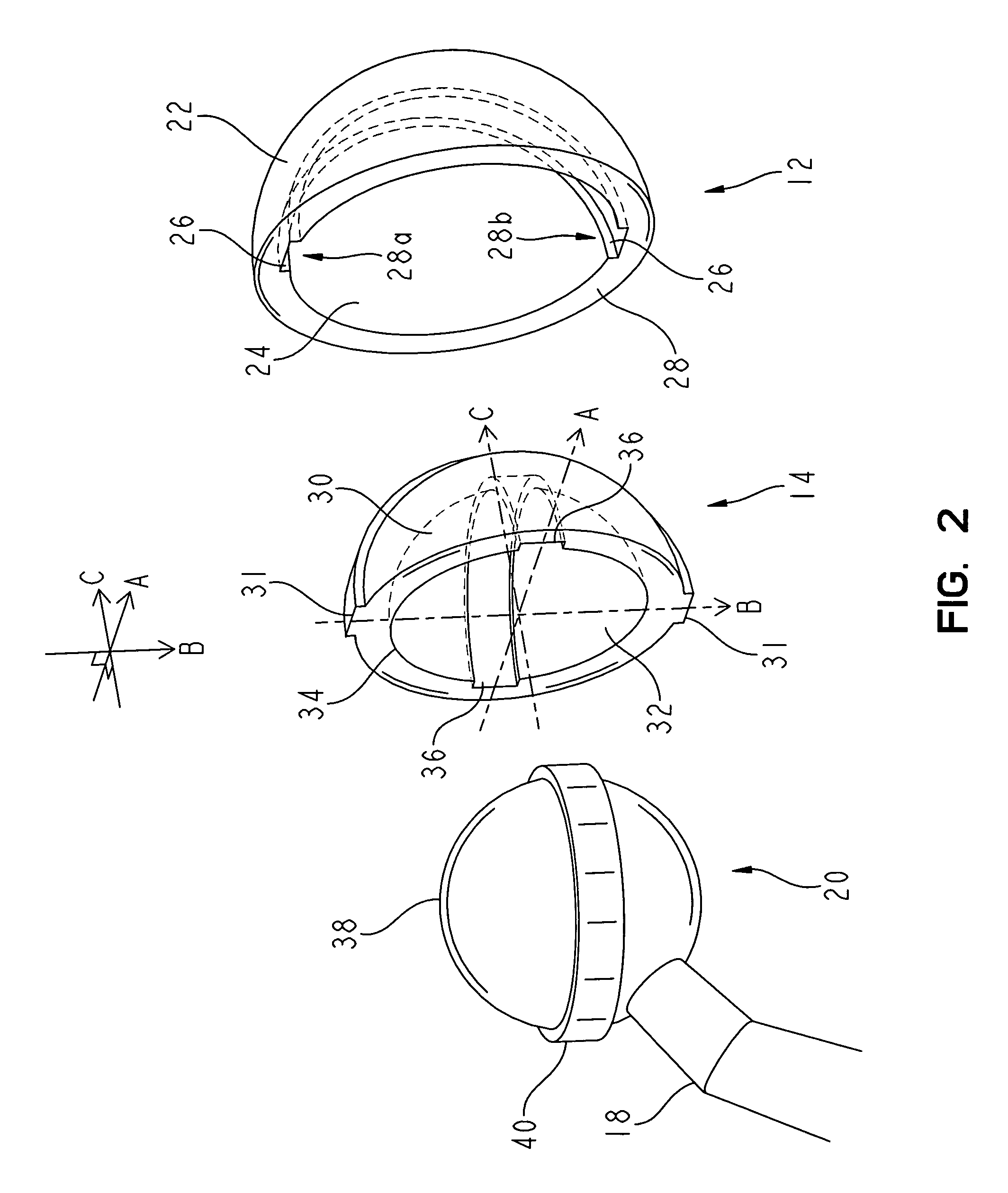
[0026]FIG. 2 shows a fragmentary, enlarged and exploded view of the implant arrangement 10 without the patient bone structure. As shown in both FIG. 1 and FIG. 2, the acetabular shell 12 includes an outer surface 22 having a generally rounded shape,...


PUM


Abstract

A prosthetic implant includes first, second and third components. The first component is configured to be disposed within the acetabulum. The second component is in a load bearing relationship with the first component, and is operable to rotate in a first axis of rotation. The second component is inhibited from movement in a second axis of rotation. The third component is in a load bearing relationship with the second component. The third component is operable to rotate in the second axis of rotation, but is inhibited from movement with the first axis of rotation.

Description

FIELD OF THE INVENTION[0001]The present invention relates generally to prosthetic orthopaedic implants, and more particularly, to joint prosthetic implants.BACKGROUND OF THE INVENTION[0002]Many orthopaedic procedures involve the implantation of prosthetic devices to replace badly damaged or diseased bone tissue. Common orthopaedic procedures that involve prosthetic devices include total or partial hip, knee and shoulder replacement. Hip replacement involves total or partial replacement of the hip ball and socket joint.[0003]A total hip replacement procedure typically involves the implantation of two main component systems: the femoral component and an acetabular component. The femoral component includes a rigid stem that is anchored within the existing femur and also includes a head that replaces the natural hip joint femoral head. The acetabular component is secured within the acetabulum of the patient and serves as a bearing surface for the head of the femoral component.[0004]Hist...

Claims


Application Information

Patent Timeline
Patent Type & Authority Patents(United States)
IPC IPC(8): A61F2/32A61F2/00A61F2/30A61F2/34A61F2/36A61F2/46
CPCA61F2/32A61F2310/00179A61F2/3662A61F2/4684A61F2002/30016A61F2002/30387A61F2002/304A61F2002/30428A61F2002/30604A61F2002/3065A61F2002/30685A61F2002/30937A61F2002/3208A61F2002/3493A61F2002/3611A61F2002/3617A61F2220/0025A61F2250/0019A61F2310/00029A61F2/36A61F2002/30652
Inventor HANES, MARK D.
Owner DEPUY PROD INC
Why Eureka
Try Eureka