Inspection apparatus and inspection method

a technology of inspection apparatus and inspection method, which is applied in the direction of optical radiation measurement, luminescent dosimeter, fluorescence/phosphorescence, etc., can solve the problems of difficult to accurately check the authenticity of banknotes and other problems, and achieve the effect of accurate detection of fluorescent components in target objects, reducing load and increasing scal

Inactive Publication Date: 2006-09-19
COPAL CO LTD
View PDF9 Cites 4 Cited by
  • Summary
  • Abstract
  • Description
  • Claims
  • Application Information

AI Technical Summary

Benefits of technology

[0008]The inspection apparatus of this type could fail to accurately inspect the target object unless the output value of the light-receiving device (i.e., the quantity of the fluorescence generated from the target object) should be controlled in a fixed state against temperature. For this reason, the fluorescent member is located on the conveyance path as described above, and the light-receiving device receives the fluorescence generated from the fluorescent member, prior to the inspection of the target object, to detect the quantity of the fluorescence generated from the fluorescent member. A temperature characteristic of the fluorescence generated from the fluorescent member is equivalent to a temperature characteristic of the fluorescence generated from the target object containing the fluorescent component. Therefore, the quantity of emission from the light-emitting device is preliminarily corrected based on the quantity of the fluorescence generated from the fluorescent member, whereby the output value of the light-receiving device can be surely controlled to be approximately constant against temperature in the actual inspection of the target object. This permits the apparatus to accurately detect the fluorescent component in the target object, independent of temperature. Since the fluorescent member is placed on the conveyance path, the apparatus can be constructed with

Problems solved by technology

However, the quantity of emission from the light source varies depending upon temperature change or the like, which can result in failure in accurately meas

Method used


Image

  • Inspection apparatus and inspection method
  • Inspection apparatus and inspection method
  • Inspection apparatus and inspection method

Examples


Embodiment Construction

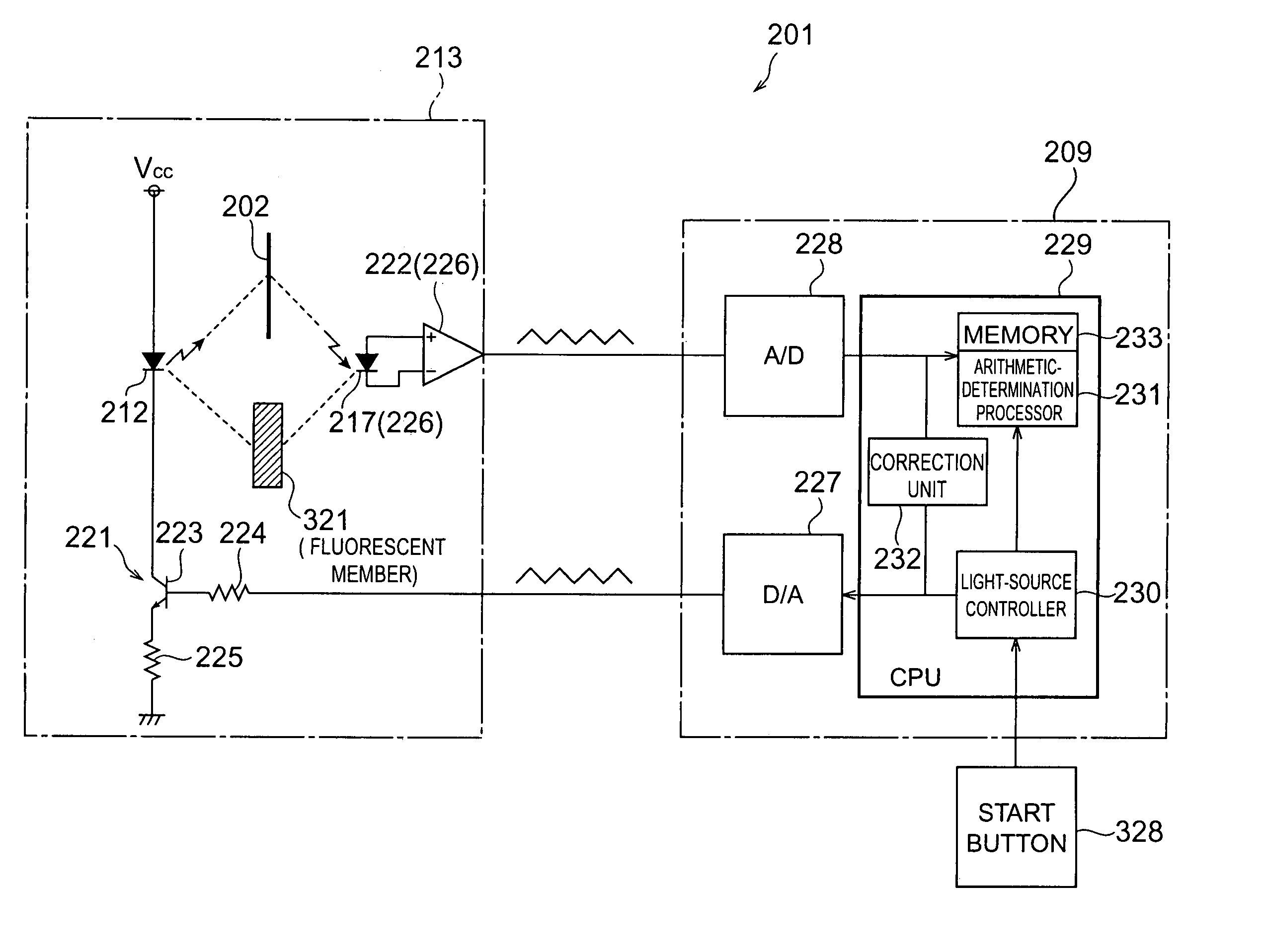
[0030]The preferred embodiments of the inspection apparatus according to the present invention will be described below in detail with reference to the drawings.

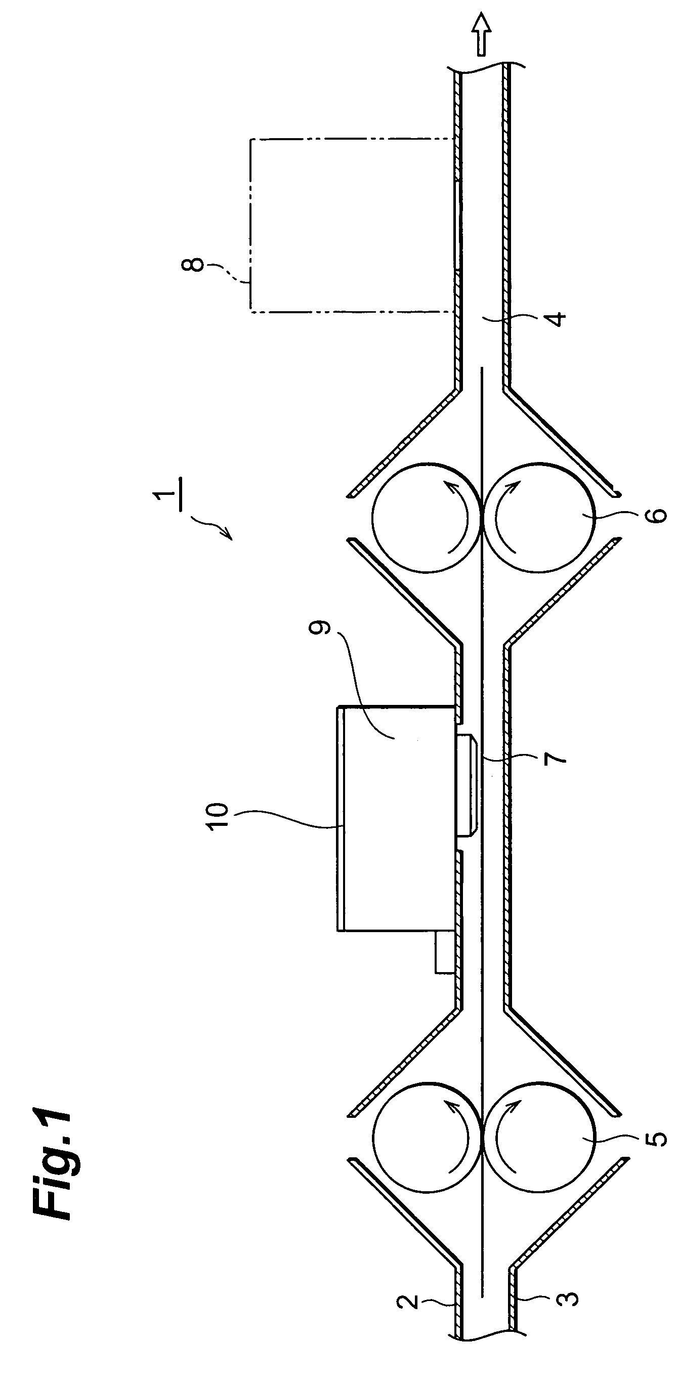
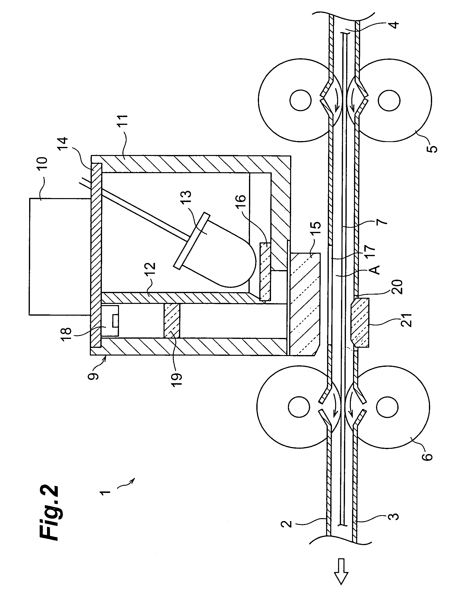
[0031]FIG. 1 is a sectional view showing a banknote inspection apparatus as an embodiment of the inspection apparatus according to the present invention. The banknote inspection apparatus 1 is configured to check the authenticity of banknotes and determine denominations thereof. The banknote inspection apparatus 1 has a conveyance path 4 formed between an upper guide plate 2 and a lower guide plate 3. Conveyance rollers 5, 6 are placed midway on the conveyance path 4, and a banknote 7 is conveyed toward the discharge side by the conveyance rollers 5, 6.

[0032]A banknote recognizing unit 8 for discriminating a denomination of banknote 7 is placed midway on the conveyance path 4. The banknote recognizing unit 8 has a light source for illuminating the surface of banknote 7, and a CCD camera for imaging the surface of banknote 7, ...


PUM


Abstract

A banknote inspection apparatus has a conveyance path, and midway of this conveyance path there are conveyance rollers for conveying a banknote, and a fluorescence sensor for detecting a fluorescent component included in the banknote. The fluorescence sensor has a housing and in this housing there are a light-emitting device for emitting light toward a banknote, and a light-detecting device for detecting fluorescence emitted from the surface of the banknote irradiated with ultraviolet light. A fluorescent member that generates fluorescence in response to the light emitted from the light-emitting device is placed in an inspection area of the conveyance path. In inspection of the banknote, the quantity of fluorescence from the fluorescent member is first detected, and the quantity of the light emitted from the light-emitting device is corrected based on the quantity of the fluorescence detected. Then the content of the fluorescent component in the banknote is detected in that state.

Description

BACKGROUND OF THE INVENTION[0001]1. Field of the Invention[0002]The present invention relates to inspection apparatus and method for checking the authenticity of banknotes, chits, etc., for discriminating types thereof, and so on.[0003]2. Related Background Art[0004]The conventional inspection apparatus for checking the authenticity of banknotes include, for example, those described in Document 1 (JP-A-9-507326) and Document 2 (JP-A-10-40436). The inspection apparatus described in these documents are configured to illuminate a banknote with ultraviolet light from a light source, measure a level of ultraviolet light reflected from the banknote, measure a quantity of fluorescence generated in the banknote, and compare the measurement levels with their respective reference levels, thereby checking the authenticity of the banknote.SUMMARY OF THE INVENTION[0005]However, the quantity of emission from the light source varies depending upon temperature change or the like, which can result i...

Claims


Application Information

Patent Timeline
IPC IPC(8): G06K9/74G01J1/32G01N21/64G01N21/89G07D7/12
CPCG01N21/643G07D7/122G01N21/89G07D7/1205
Inventor KAMIJO, HIDEAKI
Owner COPAL CO LTD
Why Eureka
Try Eureka