System and method for detecting roll rate sensor fault

Inactive Publication Date: 2006-09-19
FORD GLOBAL TECH LLC
View PDF4 Cites 20 Cited by
  • Summary
  • Abstract
  • Description
  • Claims
  • Application Information

AI Technical Summary

Problems solved by technology

Sensor fault is not always detectable by sensor self test and / or system electronic monitoring, having detection relying on the fault to violate sensor specification.

Method used


Image

  • System and method for detecting roll rate sensor fault
  • System and method for detecting roll rate sensor fault
  • System and method for detecting roll rate sensor fault

Examples


Embodiment Construction

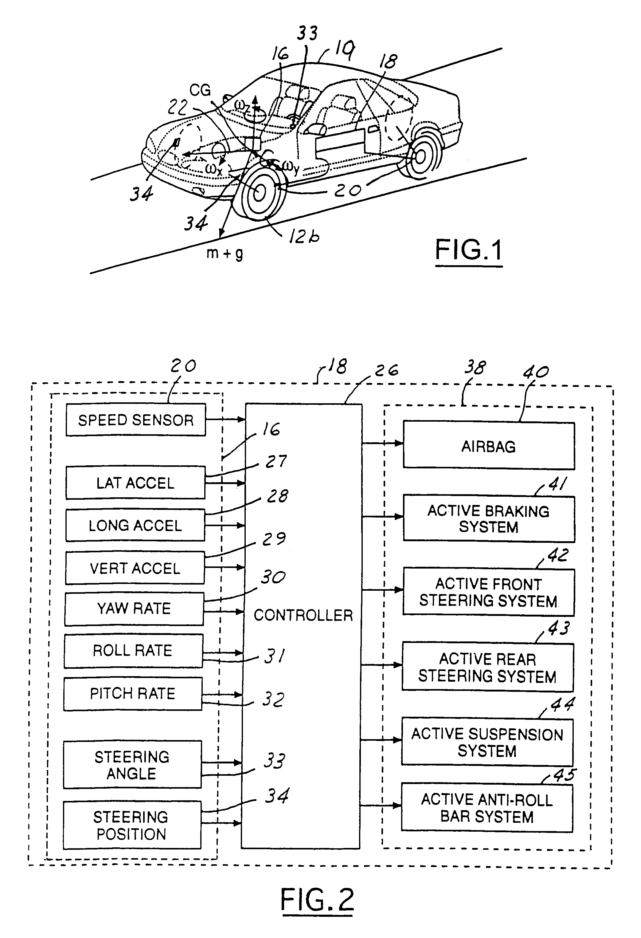
[0017]In the following figures the same reference numerals will be used to identify the same components. The present invention is preferably used to detect roll rate sensor fault in conjunction with a dynamic control system for an automotive vehicle, such as a yaw control system or a rollover control system. However, the present invention may also be used to detect roll rate sensor fault in any vehicle system including a roll rate sensor.

[0018]Referring to FIGS. 1 and 2, a safety system 18 for an automotive vehicle 19 having a sensing system 16 (sensing cluster), including a roll rate sensor 31, and a controller 26, is illustrated. Various forces and moments are acting thereon during a rollover condition.

[0019]The vehicle safety system 18 includes the sensor system 16. The sensing system 16 may use a six control sensor set including three axial accelerometers including a lateral accelerometer 27, a longitudinal accelerometer 28, and a vertical accelerometer 29 and three axial rotati...


PUM


Abstract

A control system for an automotive vehicle having a vehicle body includes a sensor cluster having a housing oriented within the vehicle body. A roll rate sensor is positioned within the housing and generates a roll rate sensor signal corresponding to a roll angular motion of the sensor housing. A controller receives the roll rate sensor signal, the controller generates a residue signal in response to a sensor error or a measurement error. The controller sets a fault condition in response to the residue signal larger than a dynamic threshold and a magnitude of the roll rate signal above a fault condition threshold. The controller sets a fault flag in response to the fault condition indicated for a predetermined time during which no double wheel lift occurs.

Description

RELATED APPLICATION[0001]The present invention is Continuation in Part application of application Ser. No. 10 / 620,881 filed on Jul. 16, 2003, now U.S. Pat. No. 6,941,205 which claimed priority to provisional application No. 60 / 400,155 filed on Aug. 1, 2002, the disclosure of which is incorporated by reference herein.TECHNICAL FIELD[0002]The present invention relates generally to automotive vehicle sensors, and more specifically, to a method and apparatus for detecting a roll rate sensor fault using functional and analytical redundancy.BACKGROUND[0003]Current rollover stability control (RSC) schemes addressing vehicle roll situations and include a variety of sensors sensing vehicle dynamic conditions. RSC systems further include a controller controlling a distributed brake pressure for reducing a tire moment such that the net moment of the vehicle is counter to the vehicle roll direction.[0004]RSC sensors include a speed sensor, a lateral acceleration sensor, a roll rate sensor, and ...

Claims


Application Information

Patent Timeline
Patent Type & Authority Patents(United States)
IPC IPC(8): B60Q1/00B60G17/016B60G17/018B60G17/0185B60G17/0195B60R16/02B60R16/023B60R21/00B60R21/01B60R21/0132B60T8/00B60T8/172B60T8/1755B60T8/24B60T8/88B60T17/22B60W30/04
CPCB60G17/0162B60G17/0185B60G17/0195B60R16/0233B60R21/01B60R21/013B60R21/0132B60T8/00B60T8/172B60T8/1755B60T8/241B60T8/243B60T8/885B60T17/22B60G17/0182B60W30/04B60G2600/08B60G2600/1871B60G2800/0194B60G2800/215B60G2800/80B60G2800/922B60R2021/0018B60R2021/01122B60R2021/01327B60T2230/03B60T2240/06B60T2270/413
Inventor TSENG, HONGTEI ERICXU, LI
Owner FORD GLOBAL TECH LLC
Why Eureka
Try Eureka