
Method and apparatus for automatically reporting of faults in a communication network

a communication network and automatic reporting technology, applied in the field of communication, can solve the problems of limiting customer choice, difficult to distinguish between telephony and telecommunication, and many problems with this kind of network architectur

Inactive Publication Date: 2006-09-19
UNIFY INC
View PDF24 Cites 57 Cited by
  • Summary
  • Abstract
  • Description
  • Claims
  • Application Information

AI Technical Summary

Benefits of technology

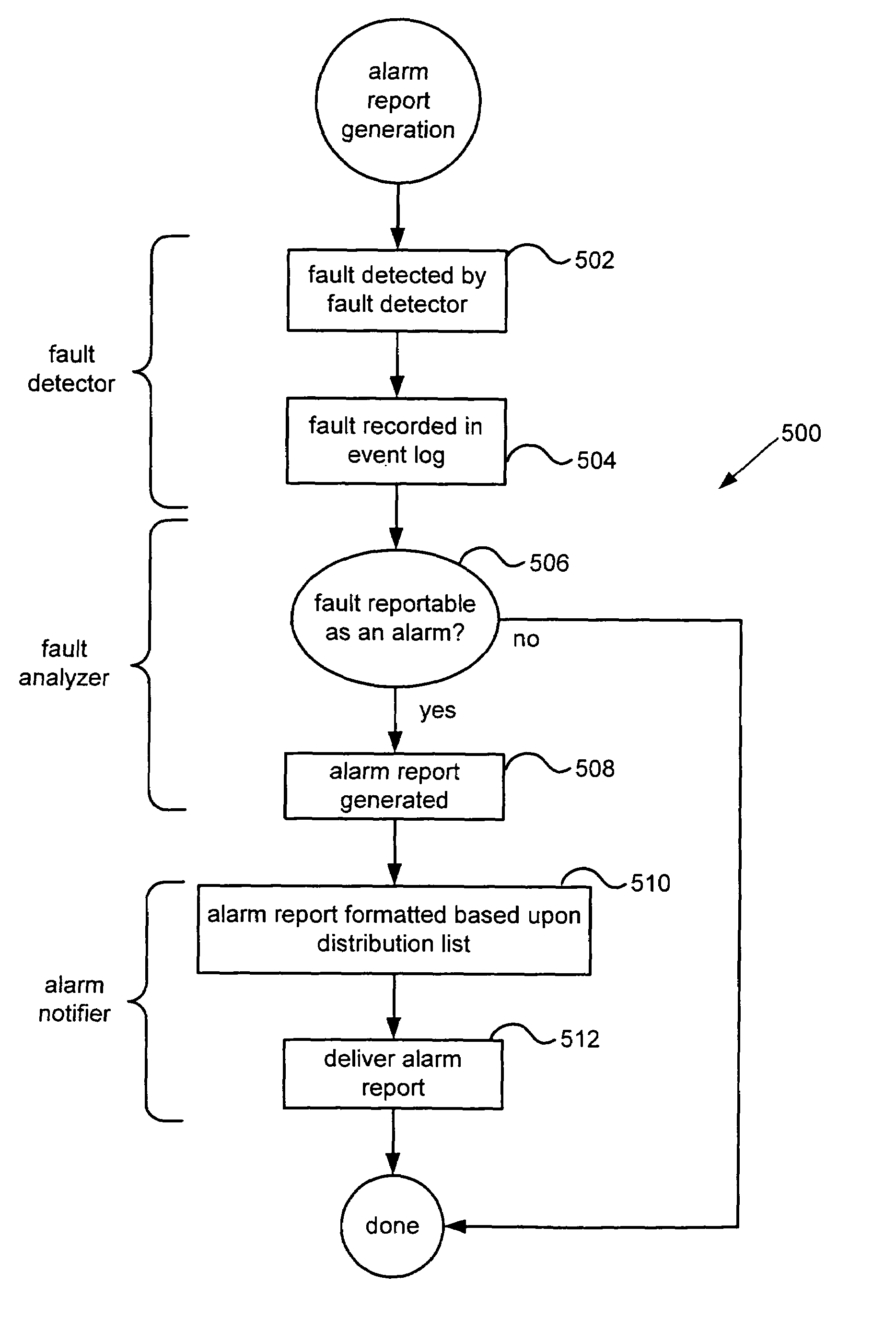
[0009]Broadly speaking, the invention relates to an improved method, apparatus and computer system for automatically reporting of faults in a telephonic network. In one aspect of the invention, a method of generating an alarm report for a distributed communication system is disclosed. When a n

Problems solved by technology

With the arrival of computers and the transmittal of digital information over telephone systems and the use of radio to transmit telephone signals, the distinction between telephony and telecommunication has become difficult to find.
Despite its popularity, there are a lot of problems with this kind of network architecture.
These problems include, 1) if the central switch dies, the phone network is dead, 2) each switching product is typically usable only within a specific size range in that scaling to the next level means throwing the old switch out and buying a new one, and 3) a closed architecture where everything from the switch to individual telephone handsets are proprietary thereby limiting customer choices.
In addition, the conventional distributed telephone system has many redundant components that will support many types of handsets, from standard analog sets to standards compliant IP telephones running H.323 over Ethernet.
Unfortunately, however, the distributed nature of the distributed network system makes the ability to identify and locate a malfunctioning component within the network very time consuming and costly.
This problem of determining the location and type of malfunction is compounded as the distributed network increases in size and complexity greatly increasing the potential downtime for those affected systems.

Method used


Image

  • Method and apparatus for automatically reporting of faults in a communication network
  • Method and apparatus for automatically reporting of faults in a communication network
  • Method and apparatus for automatically reporting of faults in a communication network

Examples


Embodiment Construction

[0018]Reference will now be made in detail to a preferred embodiment of the invention. An example of the preferred embodiment is illustrated in the accompanying drawings. While the invention will be described in conjunction with a preferred embodiment, it will be understood that it is not intended to limit the invention to one preferred embodiment. To the contrary, it is intended to cover alternatives, modifications, and equivalents as may be included within the spirit and scope of the invention as defined by the appended claims.

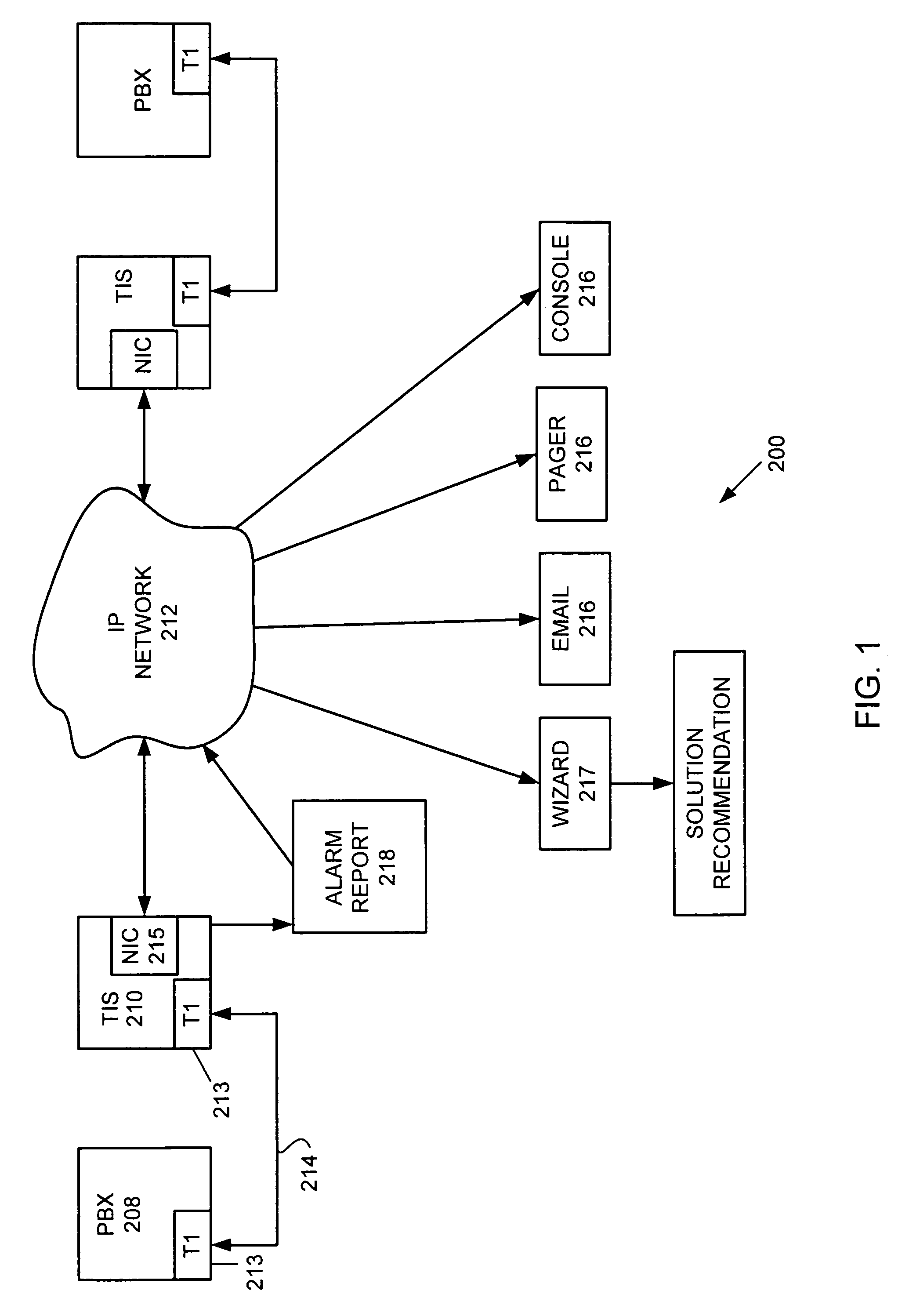
[0019]This invention is generally directed to a system for automatically identifying the location and nature of a malfunction in a distributed communication system. In a preferred embodiment, the distributed communication system is a local area network (LAN) based telephony system, also referred to as telephony over LAN (ToL)

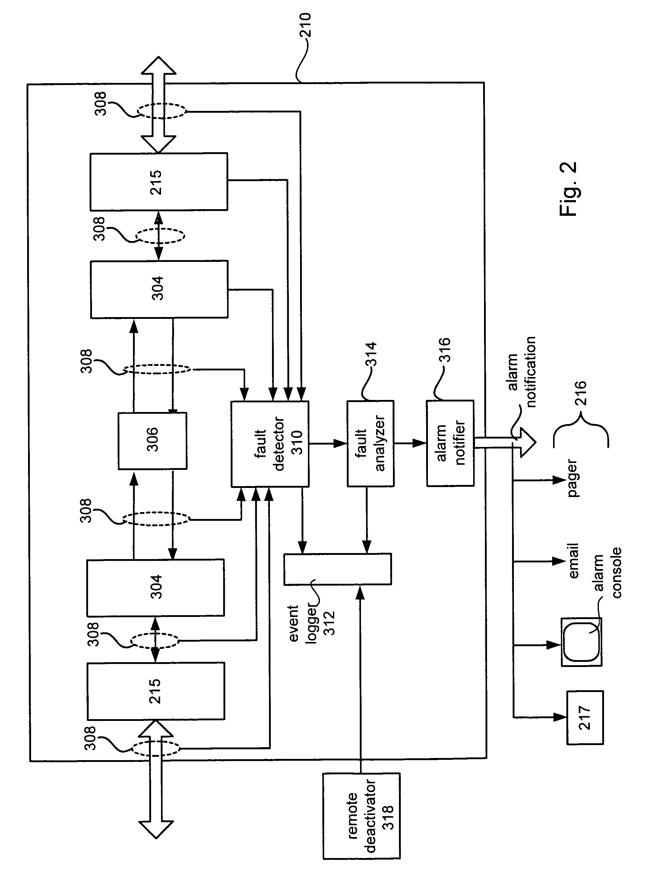
[0020]A monitoring system included in a computer based gateway, also referred to as a telephony intranet server (TIS), is arranged to m...


PUM


Abstract

An improved method, apparatus and computer system for automatically reporting of faults in a telephonic network is described. When a network fault is detected, a determination is made by a fault analyzer whether or not the detected fault is a reportable fault. If the detected fault is a reportable fault, then an alarm report based upon the reportable fault is generated which is then distributed based upon a distribution list. The distribution list includes only those destination addresses associated with the reportable fault. The alarm report in distributed to any number and kind of communications devices such as, a pager, an email server, and a control console.

Description

BACKGROUND OF THE INVENTION[0001]1. Field of Invention[0002]The invention generally relates to the field of communications. More particularly, the invention is directed to methods and apparatus for automatically reporting faults in a distributed communication network.[0003]2. Description of Relevant Art[0004]Telephony is the technology associated with the electronic transmission of voice, fax, or other information between distant parties using systems historically associated with the telephone. With the arrival of computers and the transmittal of digital information over telephone systems and the use of radio to transmit telephone signals, the distinction between telephony and telecommunication has become difficult to find. Moreover, with the advent of Internet telephony (i.e., the use of the Internet rather than the traditional telephone company infrastructure and rate structure to exchange spoken or other telephone information), the Internet has now made available (at local phone ...

Claims


Application Information

Patent Timeline
IPC IPC(8): G06F11/00
CPCH04L41/12H04L41/0681
Inventor JAHN, JEFFREY M.GILBERT, LEROYGROSBERG, MARKFLANAGAN, MARK J.
Owner UNIFY INC
Learn More