Methods and systems of using result buffers in parity operations

a result buffer and parity operation technology, applied in the direction of instruments, coding, code conversion, etc., can solve the problems of doubling the cost of storing data, reducing the performance and availability characteristics of mirror methods, and reducing the efficiency of computations

Inactive Publication Date: 2006-09-19
HEWLETT-PACKARD ENTERPRISE DEV LP +1
View PDF8 Cites 31 Cited by
  • Summary
  • Abstract
  • Description
  • Claims
  • Application Information

AI Technical Summary

Benefits of technology

[0020]In accordance with the invention, every possible parity-related computation is identified as a different scenario. A coefficient subset is selected or computed for each different scenario and stored in a memory table during an initialization process. To perform a particular operation, its scenario is identified and the corresponding coefficient subset is located. Hardware logic is then instructed to perform the actual parity operation, using the identified coefficient subset. This allows very efficient computations, using coefficients that are computed and selected ahead of time. In one embodiment, parity segments are calculated by a parity segment calculation

Problems solved by technology

However, the mirror method is also relatively expensive, effectively doubling the cost of storing data.
The parity method is advantageous because it is less costly than the mirror method, but it also has lower performance and availability characteristics in comparison to the mirror method.
While N+2 redundancy grouping enhances data protection, it also involves more complex calculations—both in initial

Method used


Image

  • Methods and systems of using result buffers in parity operations
  • Methods and systems of using result buffers in parity operations
  • Methods and systems of using result buffers in parity operations

Examples


Embodiment Construction

Parity Operations

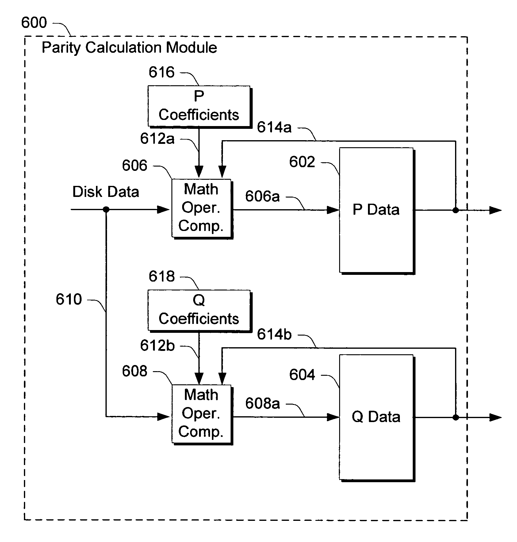
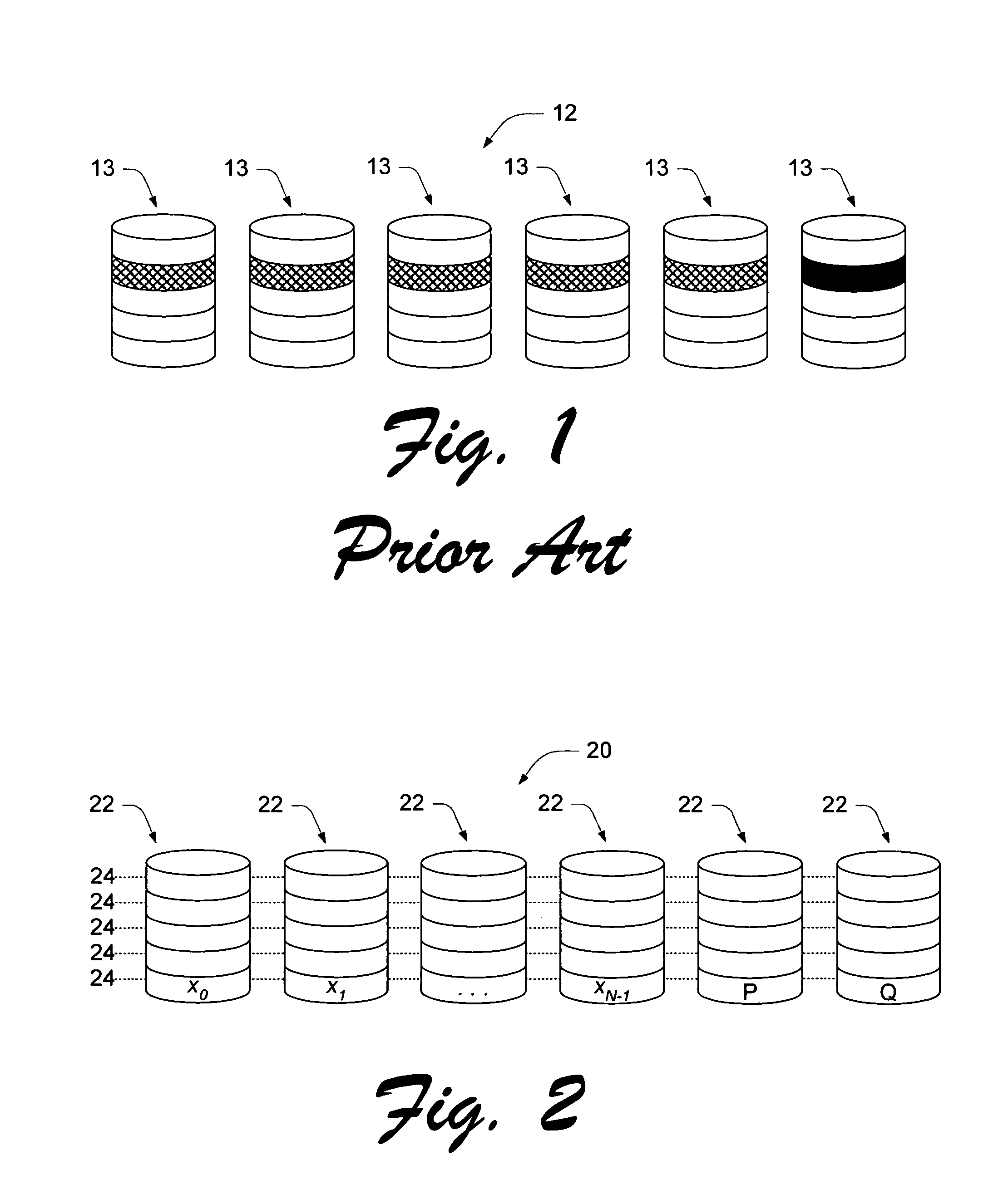
[0028]Referring to FIG. 2, a redundant data storage system 20 in accordance with the invention utilizes storage disks 22 with data stripes 24. Each data stripe 24 comprises a plurality of data segments x0 through xN−1 and at least two corresponding parity segments P and Q. P and Q are derived from the data segments x0 through xN−1, from a first set of parity coefficients p0 through pN−1, and from a second set of parity coefficients q0 through qN−1. The parity coefficients correspond to respective data segments in accordance with the equations below:

P=p0x0+p1x1+p2x2+pN−1xN−1

Q=q0x0+q1x1+q2x2+qN−1xN−1

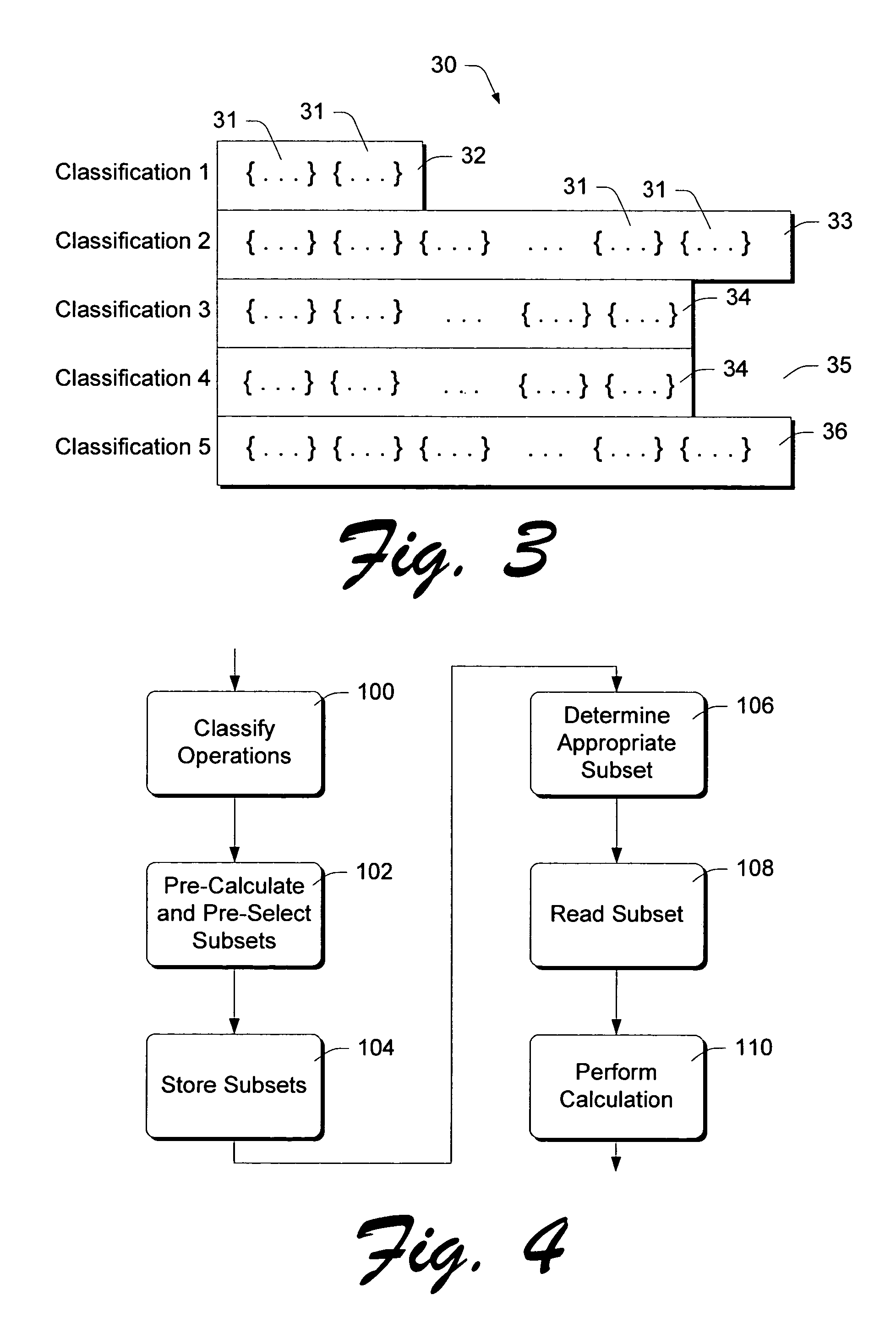
[0029]In accordance with the invention, parity operations are generally classified as parity segment generation operations, parity segment regeneration operations, and data segment reconstruction operations.

[0030]A parity segment generation operation is performed when creating a new data stripe—the parity segments are created based on completely new data.

[0031]A parity seg...


PUM


Abstract

A disk controller includes memory that is accessible by both a microprocessor and hardware parity logic. Parity-related operations are identified by scenario, and parity coefficient subsets are stored in a memory table for each different parity-related calculation scenario. To perform a particular parity-related operation, the microprocessor determines the operation's scenario and identifies the corresponding coefficient subset. The hardware parity logic is then instructed to perform the appropriate parity computation, using the identified coefficient subset. In one embodiment, parity segments are calculated by a parity segment calculation module that is embodied as an application specific integrated circuit (ASIC). The ASIC includes one or more result buffers for holding intermediate computation results, one or more mathematical operator components configured to receive data segments and coefficients associated with the data segments and operate on them to provide intermediate computation results that can be written to the one or more result buffers, and one or more feedback lines. The feedback lines are coupled between an associated result buffer and an associated mathematical operator component and provide an intermediate computation result to the math operator for use in calculating parity segments.

Description

RELATED APPLICATION[0001]This application is a continuation of and claims priority to prior application Ser. No. 09 / 808,910, filed Mar. 14, 2001 now U.S. Pat. No. 6,687,872, the disclosure of which is incorporated by reference herein.TECHNICAL FIELD[0002]This invention relates to parity operations in redundant disk drive systems, and particularly to parity operations in such systems that utilize two or more parity segments per storage stripe.BACKGROUND OF THE INVENTION[0003]Modern, high-capacity data storage systems often utilize a plurality of physical disk drives for redundant storage of data. This arrangements speeds data access as well as protecting against data loss that might result from the failure of any single disk.[0004]There are two common methods of storing redundant data. According to the first or “mirror” method, data is duplicated and stored on two separate areas of the storage system. In a disk array, for example, identical data is stored on two separate disks. This ...

Claims


Application Information

Patent Timeline
IPC IPC(8): G06F11/00G11C29/00H03M13/00G06F3/06G06F11/08G06F11/10
CPCG06F11/1076G06F2211/1057G06F2211/1054
Inventor OLDFIELD, BARRY J.RUST, ROBERT A.
Owner HEWLETT-PACKARD ENTERPRISE DEV LP
Why Eureka
Try Eureka