
Pyrotechnic detonator with an igniter support of plastic with an integrated metal insert

a technology of igniter support and pyrotechnic detonator, which is applied in the direction of electric fuzes, pedestrian/occupant safety arrangements, vehicular safety arrangements, etc., can solve the problems of failure of detonator operation, failure of electrical connections to develop, and high manufacturing cost, so as to reduce cost and reduce cost

Inactive Publication Date: 2006-09-26
AUTOLIV DEV AB
View PDF10 Cites 17 Cited by
  • Summary
  • Abstract
  • Description
  • Claims
  • Application Information

AI Technical Summary

Benefits of technology

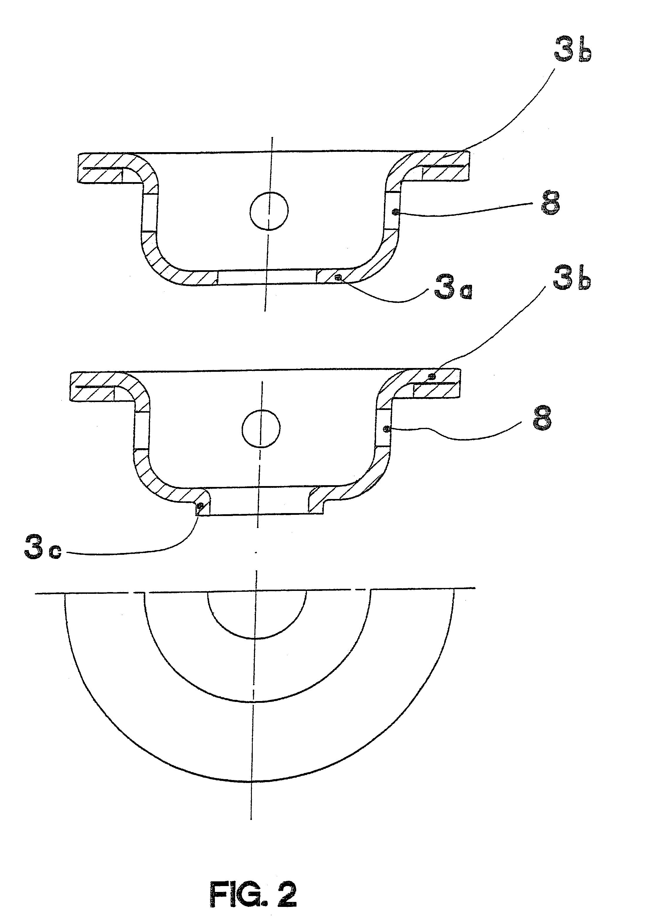
[0014]For better bonding with the plastic, holes are advantageously provided in the metal insert.
[0016]This manner of manufacture is very economical, since both the insert and the subsequent injection molding process can be performed at low cost. Both manufacturing methods can be practiced with multiple tools, resulting in an additional cost reduction.
[0017]In this arrangement the metal insert or stamped or bent piece provide the mechanical support which can be made with equal strength and less wall thickness due to their stiffness than a turned or milled part. Thus a saving of weight can additionally be achieved.
[0020]To increase safety against electrostatic discharges (ESD) between the ignition element and the metal casing, the plastic of the igniter support can be doped with mica. This results in a high-resistance plastic that develops low resistance at high voltage, and bleeds off the ESD discharges so that no unintentional firing takes place.

Problems solved by technology

This method of manufacture is very cost-intensive.
In practice, it has developed in the conventional igniter supports that, due to stray conductive impurities, e.g., metal chips, an unwanted electrical connection can develop in the contact region between the ignition element and the igniter support which can result in failure of the detonator to operate.
In the case of a plastic igniter support such electrical connections cannot develop since it insulates in the contact area.

Method used


Image

  • Pyrotechnic detonator with an igniter support of plastic with an integrated metal insert
  • Pyrotechnic detonator with an igniter support of plastic with an integrated metal insert
  • Pyrotechnic detonator with an igniter support of plastic with an integrated metal insert

Examples


Embodiment Construction

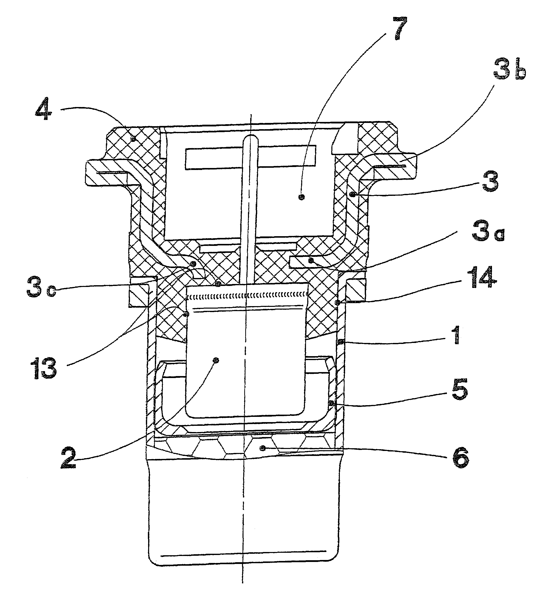
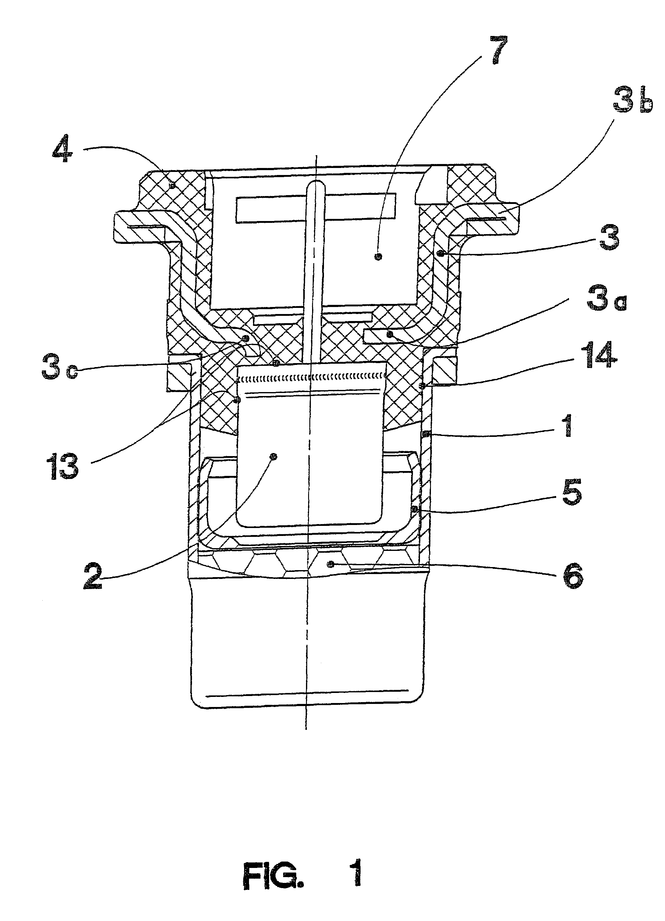
[0027]In FIG. 1 a typical detonator is shown, into which the igniter support 4 made of plastic can be inserted.

[0028]As it can be seen, the ignition element 2 is partially encased in the igniter support 4 and the metal insert 3 is integrated in it. The igniter support 4, in turn, is connected to an envelope 1 which in its lower portion contains a sealing cup 5 which protects the booster charge 6 in its installed state against moisture and thus assures the operation of the detonator throughout the time of its use.

[0029]To improve the seal in area 13 between the ignition element 2 and the plastic of the igniter support 4 and area 14 between the envelope 1 and the plastic of the igniter support 4 a vapor block can be installed. This can be achieved, for example, by wetting the ignition element 2 with an appropriate sealant which becomes effective after the injection molding, because of the heat it introduces and / or the shrinkage of the plastic onto the ignition element 2. Another way o...


PUM


Abstract

The invention relates to a pyrotechnic detonator with an igniter support of plastic, which bears an ignition element. A cylindrical metal housing is fastened to the igniter support, into which the ignition reaches. A booster charge is arranged in the metal housing. To improve seal tightness and lower the manufacturing costs, for mechanical support a metal insert is integrated into the igniter support, the metal insert being encased by the plastic of the igniter support.

Description

FIELD OF THE INVENTION[0001]The invention relates to a pyrotechnic detonator with an igniter support of plastic.BACKGROUND AND SUMMARY OF THE INVENTION[0002]DE-A1-199 60 642, which forms the genus, describes a pyrotechnic detonator with an igniter support of plastic. An igniter element is integrated into the igniter support, and its active part protrudes from the igniter support and reaches into a metal case which is fastened to the detonator holder. A booster charge is contained in the metal case.[0003]The igniter support of plastic serves the purpose of fixing the ignition element in the metal case in a mechanically secure manner. In addition, it must assure that, when the detonator operates, no gas can escape between the plastic igniter support / ignition element and / or the plastic detonator holder / metal case.[0004]On account of the need for mechanical strength in the operation of the detonator, in conjunction with the complex form in the contacting area of the ignition element, th...

Claims


Application Information

Patent Timeline
Patent Type & Authority Patents(United States)
IPC IPC(8): B60R21/26F42B3/10F42B3/18F42B3/26
CPCF42B3/26
Inventor BREDE, UWEBERENZ, EDUARDBRETFELD, ANTONFRANK, HARALDKNAUSS, JURGEN
Owner AUTOLIV DEV AB
Learn More