
Zero flow fireproof quick disconnect coupling

a quick disconnect and coupling technology, applied in water installations, thin material processing, construction, etc., can solve the problems of inability to readily adapt to use, the ever increasing demand for qdc couplings, and the difficulty of qdc manufacturers to meet the demand of couplings. achieve the effect of quick disconnect coupling

Active Publication Date: 2006-09-26
PARKER INTANGIBLES LLC
View PDF12 Cites 17 Cited by
  • Summary
  • Abstract
  • Description
  • Claims
  • Application Information

AI Technical Summary

Benefits of technology

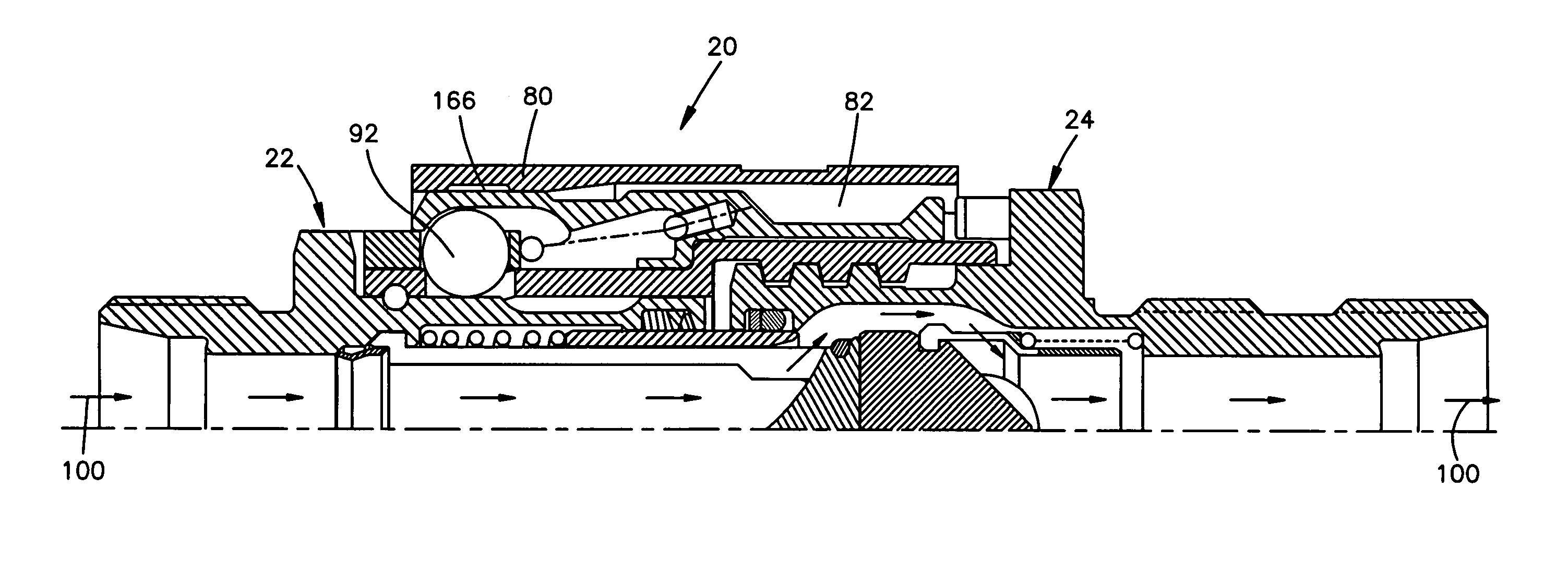
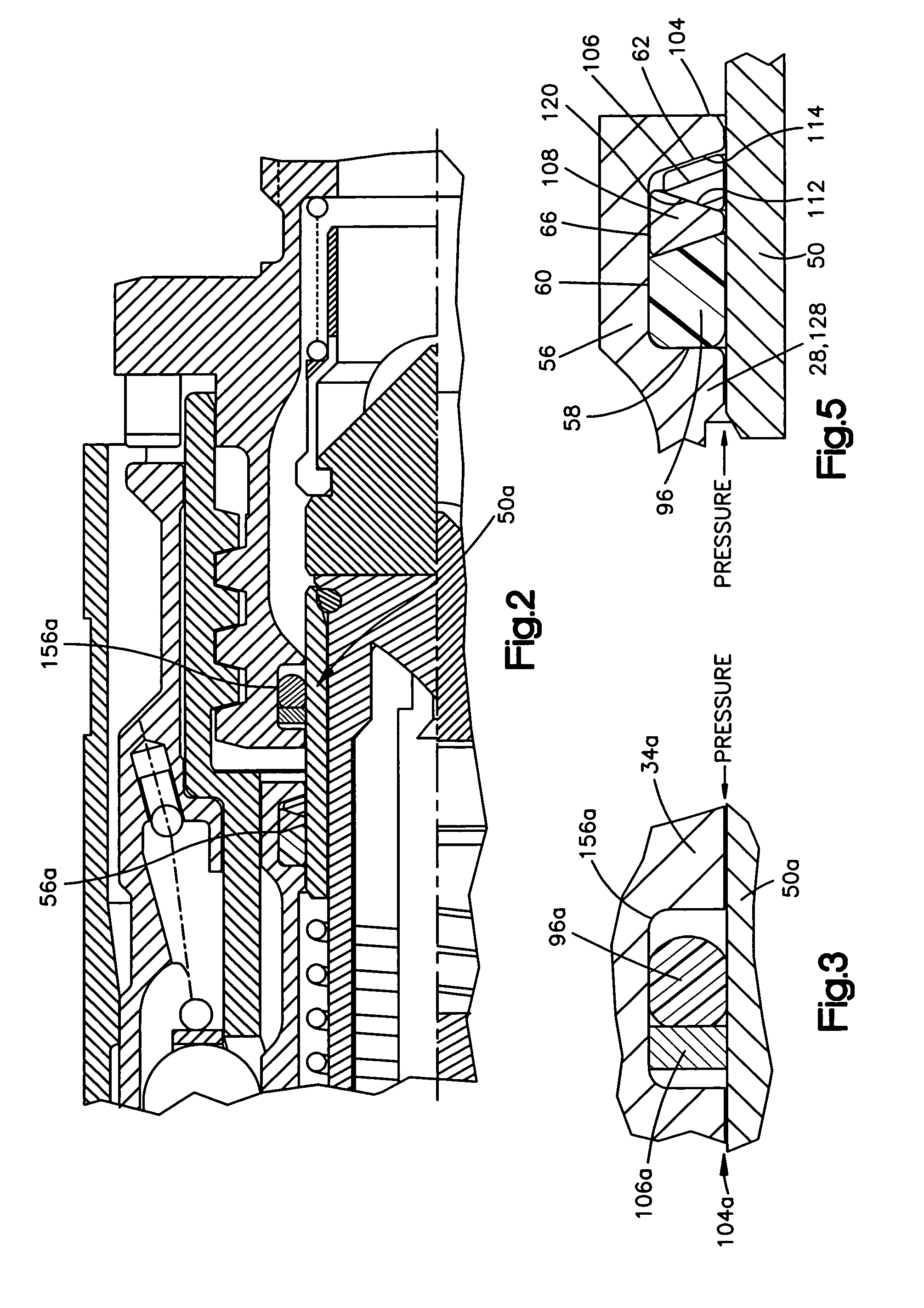
"The present invention provides an improved zero flow fireproof quick disconnect coupling structure that meets industry specifications such as SAE AS 1055. The coupling is made up of a female coupler assembly and a male nipple assembly that are connected together through complementary fastening members. The female coupler assembly includes a housing with a first and second through bore, a support member, a hollow sleeve member, a first sealing assembly, and a first elastomeric seal member. The male nipple assembly includes a housing with a first and second through bore, a poppet, and a second sealing assembly. The improvement features a unique pair of backup rings that are located in recesses in the housings and a metallic insulating sleeve that surrounds the actuating sleeve. The patent text also describes the angulations of the sealing assemblies and the material compositions of the backup rings."

Problems solved by technology

One of the more difficult challenges that QDC manufacturers face today is the ever increasing demand for such couplings to be resistant to onboard fire during flight or operation.
The metal “C” ring and other variations set forth in this reference require substantial force for actuation and cannot be readily adapted for use in quick disconnect applications since this type of metal seal requires not only substantial force to operate but also has a narrow functional scope.
However, this reference patent pertains to non-analogous art, namely by being used in a fuel nozzle used to inject fuel in a jet engine.

Method used


Image

  • Zero flow fireproof quick disconnect coupling
  • Zero flow fireproof quick disconnect coupling
  • Zero flow fireproof quick disconnect coupling

Examples


Embodiment Construction

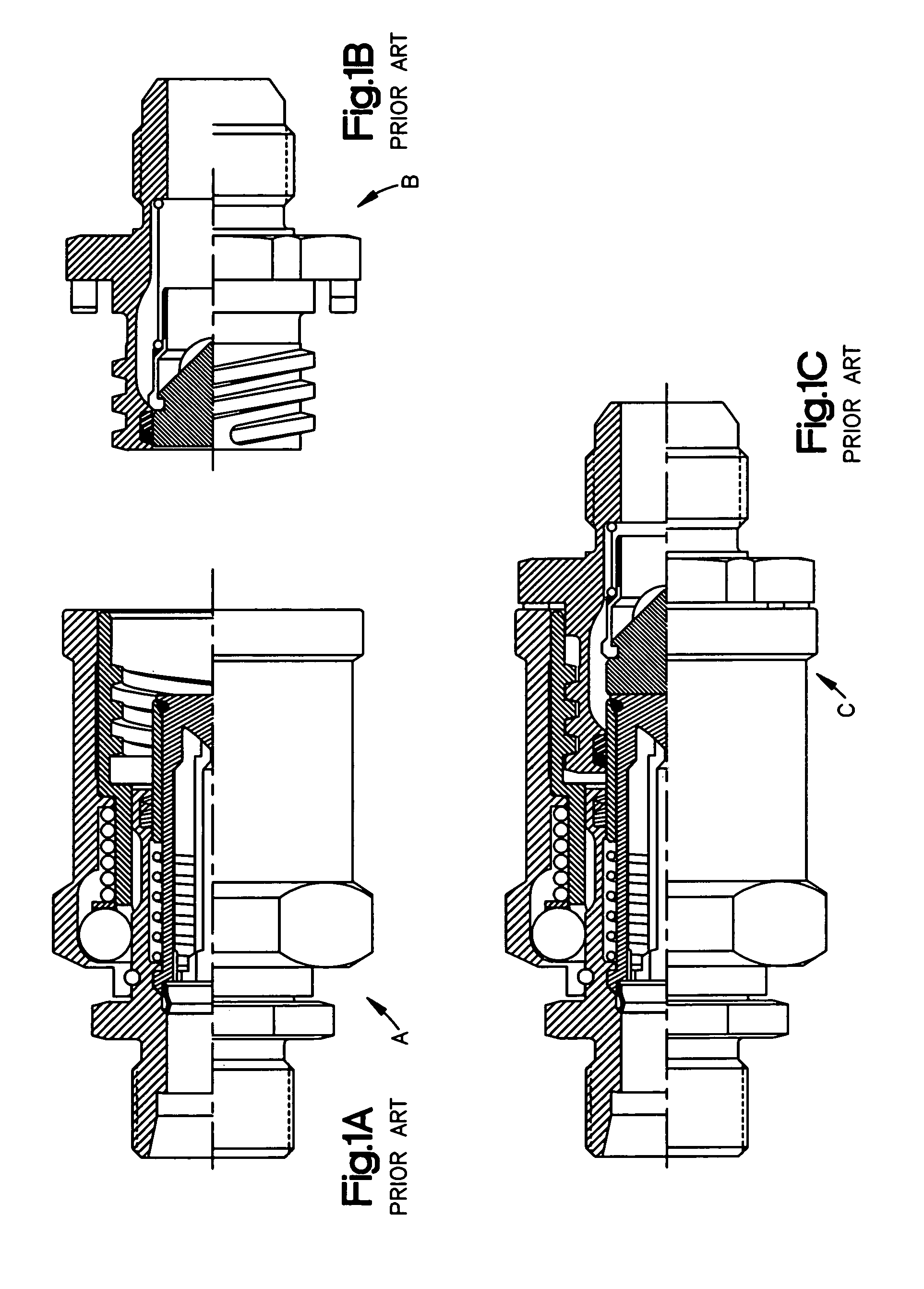
[0047]Referring now to the several drawings, illustrated in FIG. 1A is a typical uncoupled coupler of female portion A of a prior art QDC (Quick Disconnect Coupling), with FIG. 1B illustrating a typical uncoupled nipple or male portion B of a prior art QDC, while FIG. 1C illustrates a typical coupled assembly C of prior art QDC components A and B. The mating thread portions of components A and B, in assembly C, are locked by tang and slot engagement in a well-known manner. These typical prior art QDC components and coupling are typical of those illustrated and discussed in more detail, on pages 1–3 of Catalog 106-THREAD (dated September 1996) as the Stratoflex Symetrics Thread-Lok, Quick Connect Valve Couplings, manufactured and marketed by the Parker-Hannifin Corporation. The threaded coupling used to illustrate the baseline or existing prior art structures is but one of a multiple of different style QDCs where the present invention can be implemented. These other couplings can, fo...


PUM


Abstract

In an improved quick disconnect coupling comprised of operator-actuated coupler and nipple assemblies, the former including an actuating sleeve, with the coupled assemblies having first and second sealing assemblies respectively, wherein the improvement comprises, in combination, that each of the sealing assemblies includes, in addition to the known torodial sealing element, a first non-continuous metallic backup ring and a second non-metallic backup ring interposed between the torodial sealing element and the first backup ring, both backup rings being of generally truncated triangular shape, in cross section; and a metallic insulating sleeve, surrounding the actuating sleeve while being substantially fully radially spaced therefrom, via a peripheral air gap, except for a band portion at one end thereof, this band being interference-fitted on a corresponding portion of the actuating sleeve and including a plurality of axially-extending, spaced, scalloped recesses defining an additional insulating air space and having spaced boundaries that provide surfaces for the interference-fitting.

Description

CROSS-REFERENCE TO RELATED CASES[0001]The present application claims the benefit of the filing date of U.S. Provisional Application Ser. No. 60 / 525,011, filed Nov. 25, 2003, the disclosure of which is incorporated herein by reference.FIELD OF THE INVENTION[0002]The present invention pertains to Zero Flow Fireproof Quick Disconnect Couplings utilized in hydraulic applications that are required to function in severe high temperature working environments. Specifically, this invention pertains to improvements in several structures thereof, particularly the addition of metal seals and an insulation sleeve that allow such couplings to meet the fire resistance and also the fireproof requirements, of SAE AS1055 and other such related industry specifications, with zero or very low fluid cooling flow.BACKGROUND OF THE INVENTION[0003]A hydraulic system QDC (Quick Disconnect Coupling), comprised of operatively connected nipple and coupler assemblies, provides for ease of maintenance when servic...

Claims


Application Information

Patent Timeline
Patent Type & Authority Patents(United States)
IPC IPC(8): F16L37/32F16L37/28F16L55/10
CPCF16L37/28F16L55/1026F16L2201/20Y10T137/87949
Inventor MARBAN, JOSEPH R.ERICKSON, STEVEN D.
Owner PARKER INTANGIBLES LLC
Learn More