Heat dissipating housing with interlocking chamfers and ESD resistance

a heat dissipation housing and interlocking chamfer technology, applied in the direction of sliding card holders, lighting and heating apparatus, electrical apparatus contruction details, etc., can solve the problems of large amount of functionality, damage or destruction of the system itself, and inability to be reliable, etc., to facilitate heat transfer, good heat conduction properties, and inexpensive manufacturing through stamping

Inactive Publication Date: 2006-09-26
FUJITSU LTD
View PDF18 Cites 8 Cited by
  • Summary
  • Abstract
  • Description
  • Claims
  • Application Information

AI Technical Summary

Benefits of technology

[0006]According to an embodiment of the present invention, a system is designed to facilitate heat transfer via radiation, convection and conduction from components within the system to the external environment and housing. The system includes a thermally conductive plate positioned between a surface of the housing and one or more heat generating components within the housing. The plate may include raised areas for mating with heat generating components directly or through a pad comprising complaint, thermally conductive material. The housing may include perforations covering a substantial portion of its surface area to permit air to enter the housing and cool the plate and the interior of the housing. The housing may be made of a material with good heat conduction properties, such as aluminum, and may be thermally coupled to certain temperature sensitive components within the housing for temperature regulation. The housing may be inexpensively manufactured through stamping and may include two mating pieces which interlock using chamfered and dimpled electrostatic discharge fingers. The housing may also incorporate a metal shroud for enveloping certain ESD sensitive connectors, such as optical couplers.

Problems solved by technology

As a result, today's devices and systems incorporate a large amount of functionality into a small amount of space.
Fans are problematic, however, because they are not reliable and present a single point of failure.
When a fan fails, a system may overheat thus damaging or destroying the system itself.
Heat sinks which are used within the housing of a system also present problems.
First, depending on their construction and the materials used, they may be expensive and also heavy.
In addition, heat sinks present various other disadvantages depending on the way in which they are mounted within the system.
When adhesives and clips are used to mount heat sinks to components, the attachment may not be stable or reliable and may not be well suited to certain applications.
In addition, when heat sinks are mounted on a printed circuit board, posts or standoffs may be required which may block wiring channels and take up valuable space on the substrate that could be used for other purposes.

Method used


Image

  • Heat dissipating housing with interlocking chamfers and ESD resistance
  • Heat dissipating housing with interlocking chamfers and ESD resistance
  • Heat dissipating housing with interlocking chamfers and ESD resistance

Examples


Embodiment Construction

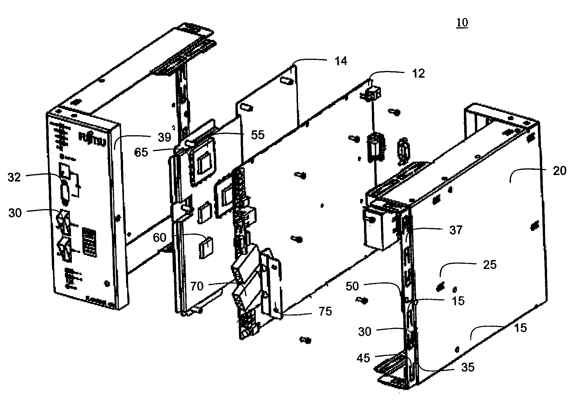
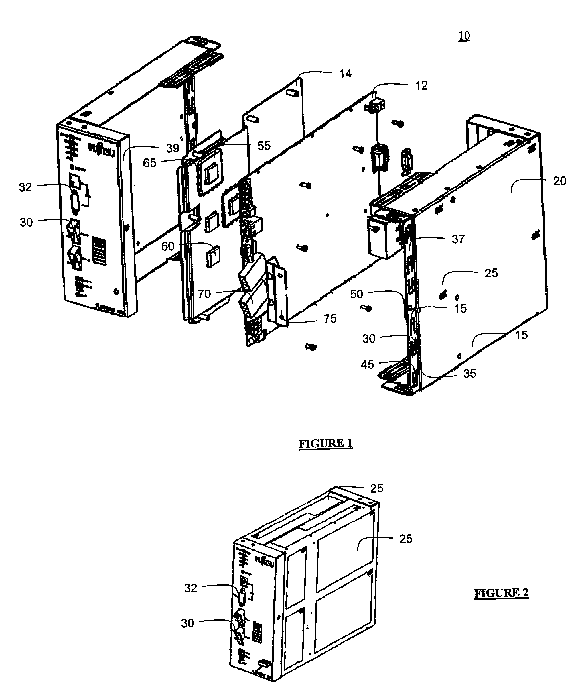
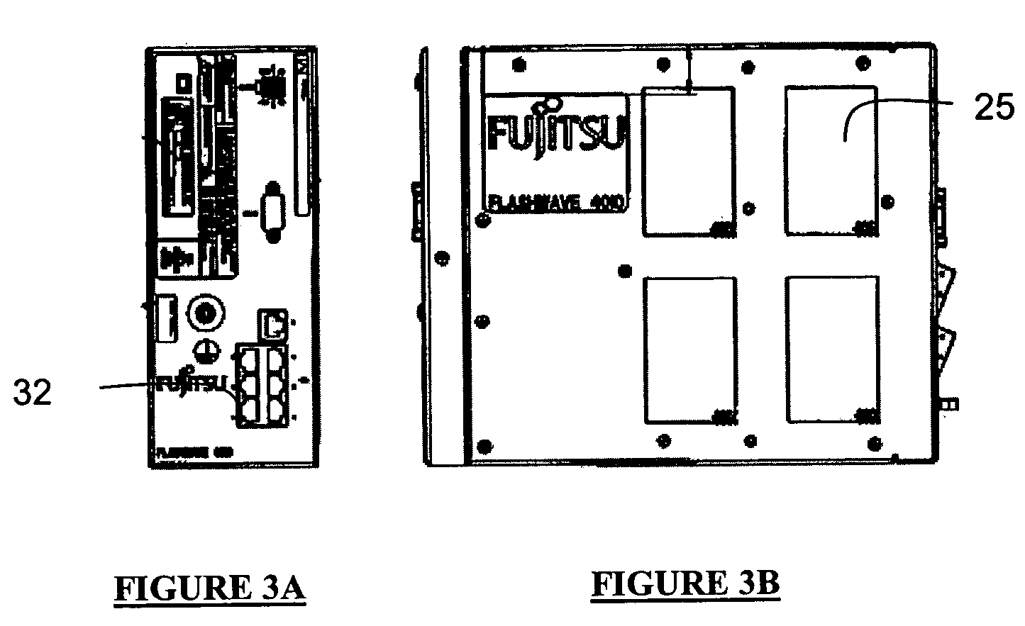
[0016]According to an embodiment of the present invention, a system is designed to facilitate heat transfer via radiation, convection and conduction from components within the system to the external environment and housing. The system includes a thermally conductive plate positioned between a surface of the housing and one or more heat generating components within the housing. The plate may include raised areas for mating with heat generating components directly or through a pad comprising complaint, thermally conductive material. The housing may include perforations covering a substantial portion of its surface area to permit air to enter the housing and cool the plate. The housing may be made of a material with good heat conduction properties, such as aluminum, and may be thermally coupled to certain temperature sensitive components within the housing for temperature regulation. The housing may be inexpensively manufactured through stamping and may include two mating pieces which ...


PUM


Abstract

A system is designed to facilitate heat transfer via radiation, convection and conduction from components within the system to the external environment and housing. The system includes a thermally conductive plate positioned between a surface of the housing and one or more heat generating components within the housing. A compliant thermally conductive material may then be placed between the heat generating components and the plate to facilitate conductive heat transfer from the component to the plate. From the plate, heat is transferred to the external environment through radiation and convection of air through perforations in the housing which cover a substantial portion of the surface area of the housing. The housing may also be inexpensively manufactured through stamping and may include two mating pieces which interlock using chamfered electrostatic discharge fingers. The housing may also incorporate a metal shroud for enveloping certain ESD sensitive connectors, such as optical couplers.

Description

FIELD OF THE INVENTION[0001]The present invention relates generally to housings for electrical systems and, more particularly, to housing systems that are inexpensive and easy to assemble and that include features that facilitate heat dissipation through the housing to the external environment.BACKGROUND OF THE INVENTION[0002]Design and manufacturing technology for electronic and optical components has advanced and continues to advance in miniaturization, density, function and performance. As a result, today's devices and systems incorporate a large amount of functionality into a small amount of space. Examples of this are laptop computers, servers, switches and other small form factor devices and systems. These systems must be kept from overheating by dissipating heat to the surrounding environment. Some components within the systems must also be given special attention either because they generate more heat than the others or because they exhibit more sensitivity to temperature ch...

Claims


Application Information

Patent Timeline
Patent Type & Authority Patents(United States)
IPC IPC(8): F28F7/00H05K7/20
CPCH05K7/1461H05K7/20445H05K7/20127
Inventor PEDOEEM, ALBERTBRAUN, WILLIE ERNSTYUAN, LANGDAYTON, COREY M.CHERRY, STEVEN M.
Owner FUJITSU LTD
Why Eureka
Try Eureka