Support clip and pilaster apparatus and method

a support clip and pilaster technology, applied in the field of support clip and pilaster apparatus and method, can solve the problems of clip, which is relatively light, can be dislodged by vibration, damage the shelf, add the inconvenience of a separate component, etc., and achieve the effect of reducing the cost and being easy to insert and remov

Inactive Publication Date: 2006-09-26
THERMO ELECTRON A DE
View PDF13 Cites 11 Cited by
  • Summary
  • Abstract
  • Description
  • Claims
  • Application Information

AI Technical Summary

Benefits of technology

[0010]The invention in some embodiments provides an apparatus system and method for retaining clips such as shelf clips in pilaster slots. The invention also in some embodiments provides this clip retaining effect without the need for additional parts or pieces, while reducing the expense associated with manufacturer of the arrangement, and also while providing an arrangement that is easy to insert and remove.

Problems solved by technology

It has been found that in this situation where the clips are merely resting in the pilaster slots, but are not supporting any other weight, the clips, which are themselves relatively light, can be dislodged by vibrations or bumps during transit.
That is, vibrations or bumps can cause the clips, which are relatively loosely fit in the slots when they are not supporting any other weight, to bounce or jiggle vertically enough so that they fall out of the slots.
This is undesirable, because the clips then fall to the bottom of the enclosure, and may become lost or misplaced or at least had to locate at some point during unpacking at the destination.
Also, even if the clips are supporting the shelf, vibration can cause the clips to disengage, and then both the shelf and clips can fall to the bottom of the cabinet, damaging the shelf.
However, this adds the inconvenience of a separate component.

Method used


Image

  • Support clip and pilaster apparatus and method
  • Support clip and pilaster apparatus and method
  • Support clip and pilaster apparatus and method

Examples


Embodiment Construction

[0027]In general, the present invention provides a clip used with a pilaster assembly, where the clip is snap-fit into the slots of the pilaster, so that the clip is retained when inserted into the slots. This provides the advantage that the clips tend not to fall out due to bumps or vibrations such as those that can occur, for example, during transport of a cabinet.

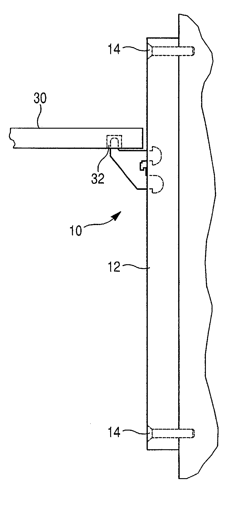
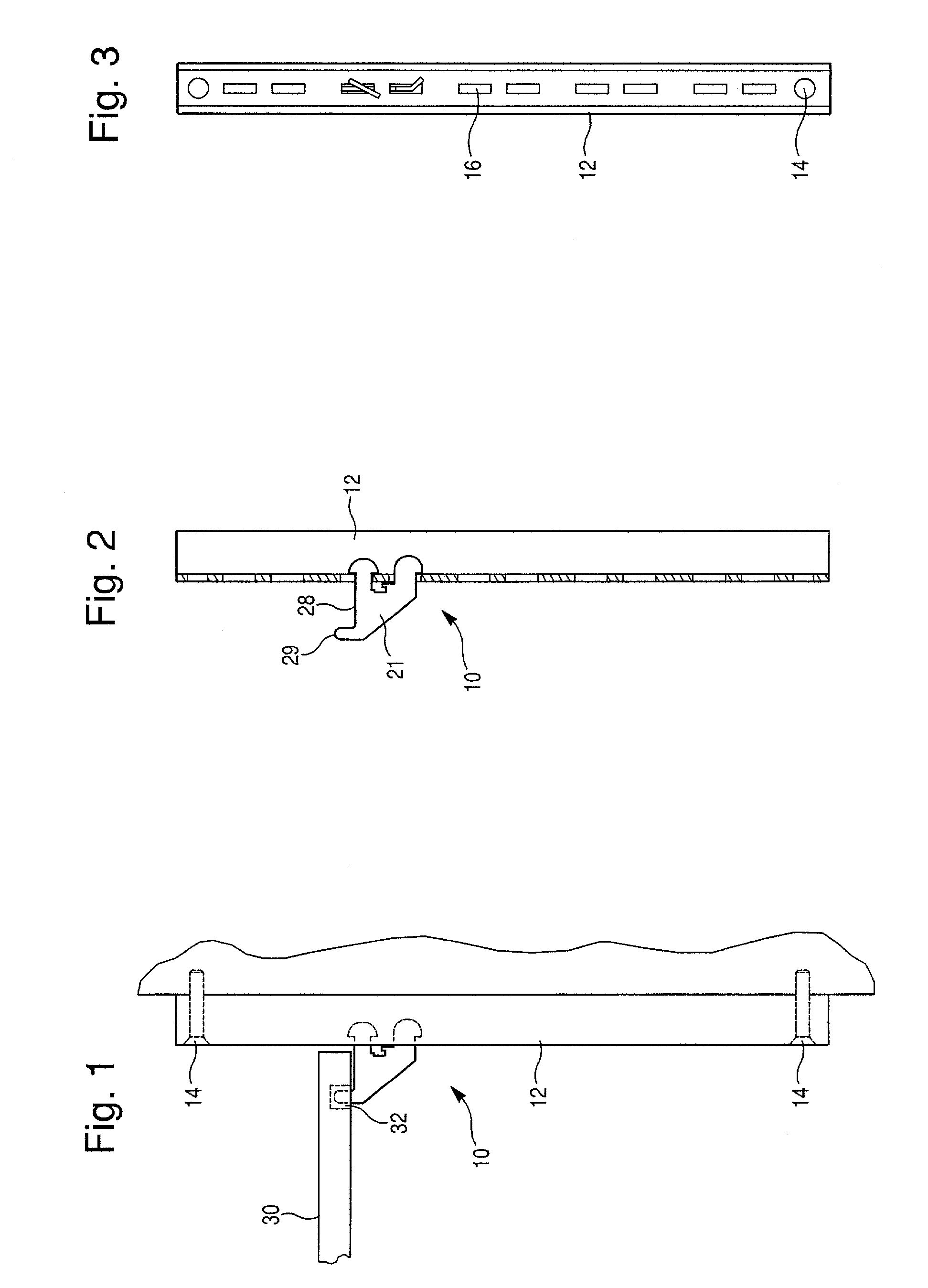
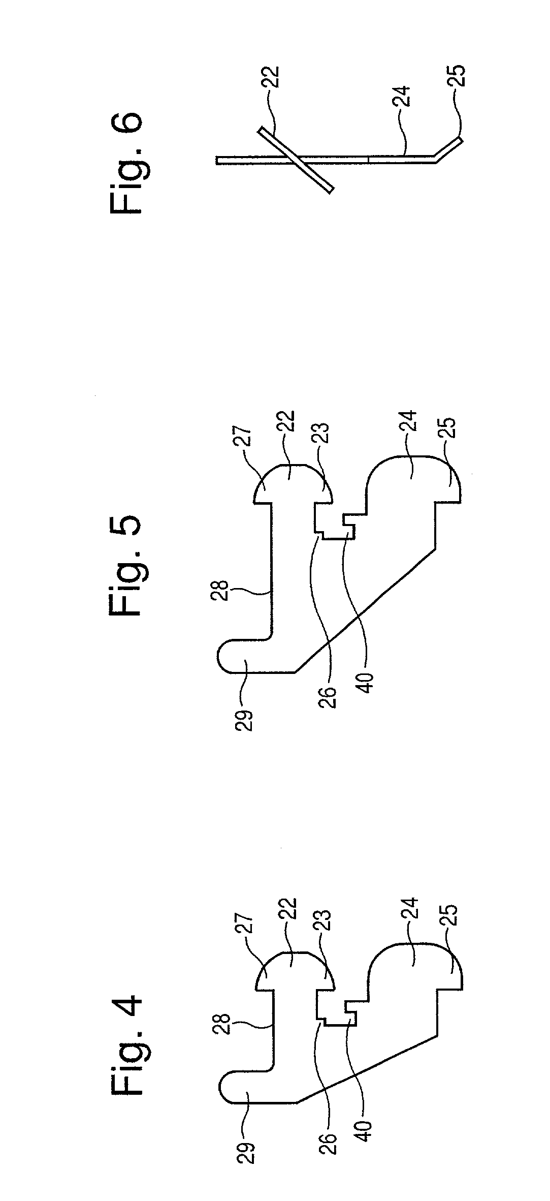
[0028]Turning now to the figures, a system 10 is shown having a pilaster strip 12 that has a plurality of fastening holes 14 that accepts screws that fasten the pilaster strip 12 to a vertical surface, such as an inside wall 15 of a cabinet. The cabinet may be an environmental control unit in the form of a refrigerator or other environmental control unit. The shelf support clips 20 each include a body 21, an upper finger 22 and a lower finger 24. The fingers each have a lower portion 23, 25 that interferes with the pilaster 12 to hold the clips 20 in place when installed. In some embodiments, both of the lower portions 2...


PUM


Abstract

A clip is used with a pilaster assembly, where the clip is snap-fit into the slots of the pilaster, so that the clip is retained when inserted into the slots. This provides the advantage that the clips tend not to fall out due to bumps or vibrations such as those that can occur, for example, during transport of a cabinet having the pilasters and clips.

Description

FIELD OF THE INVENTION[0001]The present invention relates generally to the field of pilaster strips having slots that accept removable clips for the support of various items. More particularly, some embodiments of the invention pertain to clips for supporting shelves or other items that are removably attached to pilaster strips in various cabinets, including for example various cabinet enclosures. More particularly, the invention in some embodiments relates to pilasters having slots that accept fingers that protrude into the slots. Further, some embodiments of the invention pertain to height-adjustable pilaster and clip arrangements.BACKGROUND OF THE INVENTION[0002]It is known in a wide variety of applications to use a vertical pilaster strip having a plurality of slots in combination with removable clips that have fingers that engage the slots. Pilaster and clip arrangements are well known, for example, for supporting shelves in a cantilevered fashion from a wall, so that the clip ...

Claims


Application Information

Patent Timeline
Patent Type & Authority Patents(United States)
IPC IPC(8): A47G29/02A47B57/42
CPCA47B57/42
Inventor LIN, JIANHAN
Owner THERMO ELECTRON A DE
Why Eureka
Try Eureka