Ink tank

a technology of ink tanks and ink tanks, applied in the field of ink tanks, can solve the problems of degrading the assembly lowering the manufacturing efficiency of the ink tank, etc., and achieve the effects of preventing inadvertent leakage of ink, stable negative pressure, and good printing image quality

Inactive Publication Date: 2006-09-26
CANON KK
View PDF13 Cites 23 Cited by
  • Summary
  • Abstract
  • Description
  • Claims
  • Application Information

AI Technical Summary

Benefits of technology

[0012]In the ink tank of this invention as described above, a valve and a damper are independently provided in the ink flow path between the ink accommodation space and the ink supply port; the valve is opened when the negative pressure in the ink flow path running from the ink supply port to the valve is greater than a predetermined level; and after the valve is closed, a negative pressure is created in the ink flow path from the damper to the ink supply port by an elastic recovery force of the damper. This construction makes it possible to apply a stable negative pressure at all times to the print head connected to the ink supply port, thereby forming appropriate meniscuses in the nozzles of the print head. This in turn assures appropriate ejection of ink droplets, good quality of printed image and prevention of inadvertent leakage of ink from the nozzles.

Problems solved by technology

In terms of assembly, an additional part, spring, may lower the manufacturing efficiency of the ink tank.
That is, a small component of spring must be assembled precisely by restricting its mounting position, which degrades an assembly efficiency of the ink tank.
An appropriate selection of the spring material is therefore difficult to make and, depending on circumstances, an ink composition may have to be changed.

Method used


Image

  • Ink tank
  • Ink tank
  • Ink tank

Examples


first embodiment

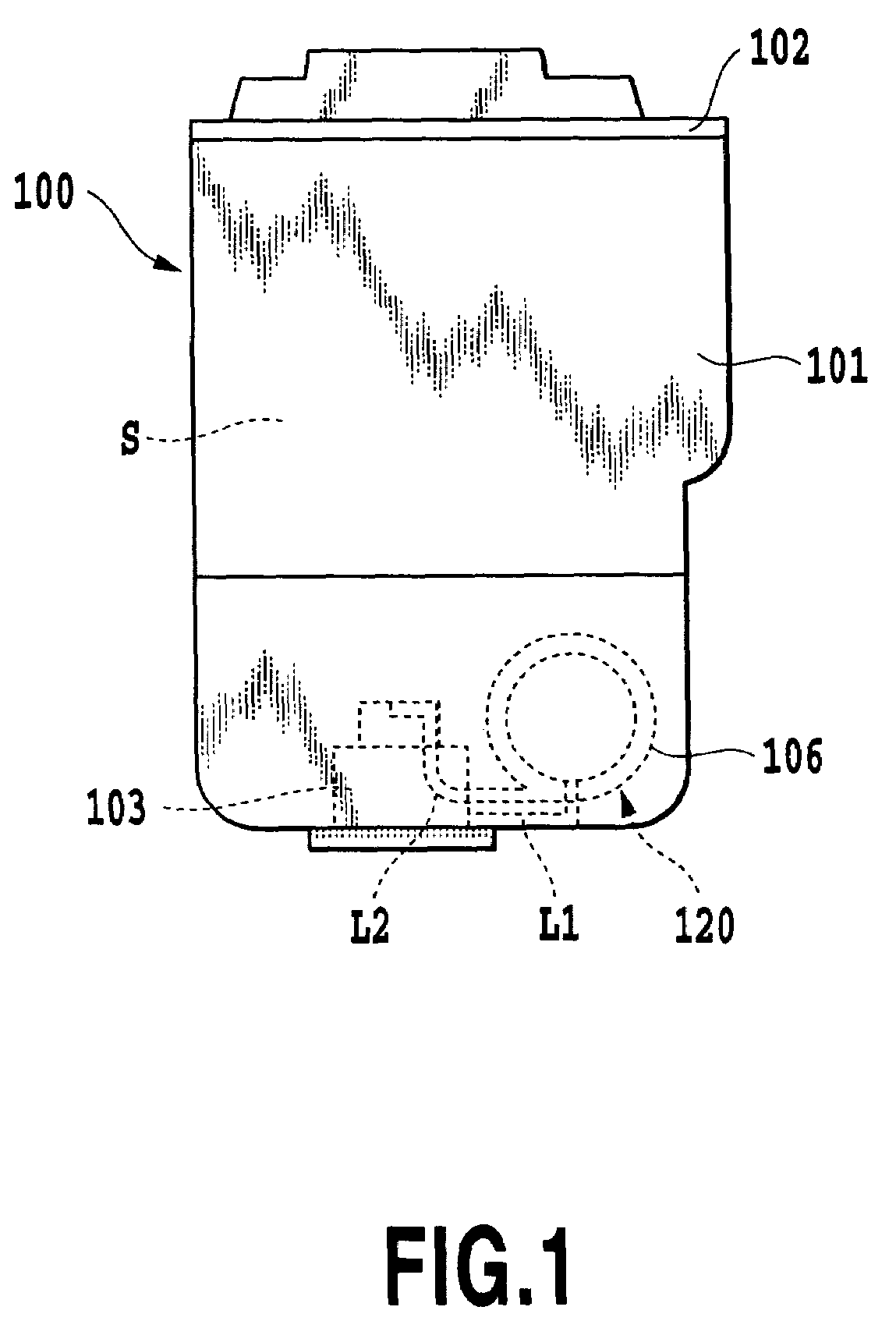
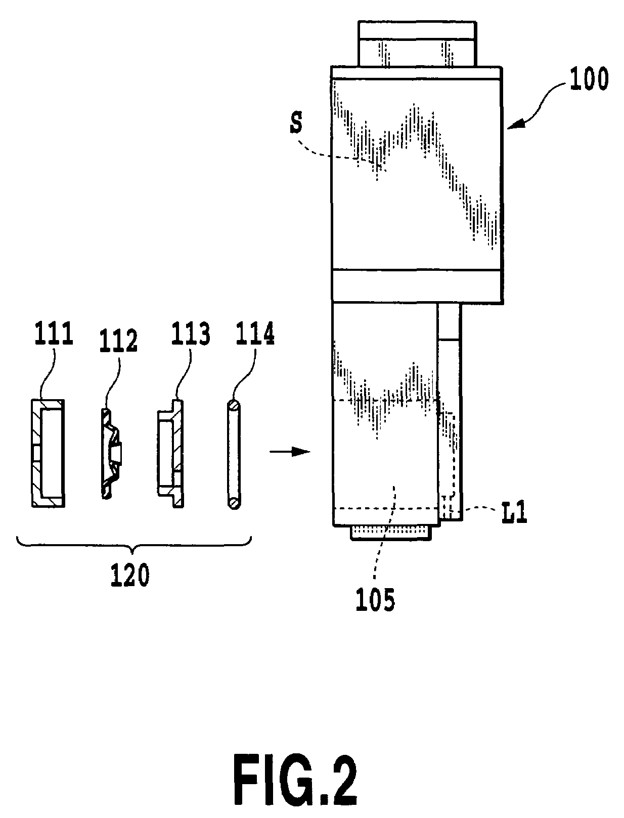
[0082]The ink tank 100 of this embodiment has a cylindrical head mounting portion 130 (FIGS. 11A and 11B) in which a tank mounting portion of the print head is inserted when the ink tank is installed in the head cartridge. The opening of the head mounting portion 130 forms the ink supply port 103 of the ink tank. A side surface of an upper part of the head mounting portion 130 is connected to the valve unit 120 through the flow path L2. An upper end of the head mounting portion 130 is formed with a through-hole 130A.

[0083]The upper end portion of the head mounting portion 130, as shown in FIG. 11A, FIG. 11B, FIG. 12A and 12B is securely and tightly fitted with a lower end portion of a damper 140 shaped like a cylinder with its head closed. The damper 140 is formed of an elastic member impermeable to liquid. The damper 140 is elastically deformable by less than a negative pressure at which the valve rubber 112 of the valve unit 120 is deformed (open). While the damper 140 is formed o...

second embodiment

[0095]Next, a second embodiment of this invention will be described.

[0096]The second embodiment has a thin damper (damper means) 180 formed in sidewalls of the ink tank as shown in FIG. 18 and FIGS. 19A–19C in place of the cylindrical dampers 140, 150, 160, 170 used in the first embodiment. The constructions of other components including the valve unit 120 are similar to those of the first embodiment.

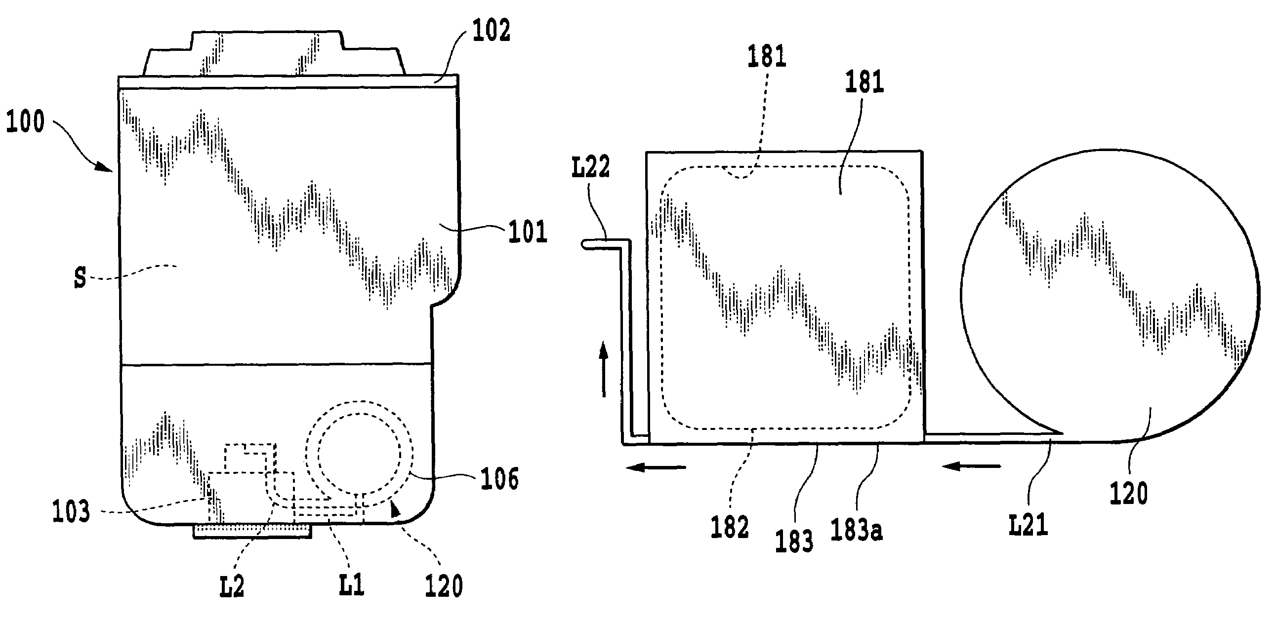
[0097]In the ink tank 100 described above, the damper 180 is provided in the ink flow path L2 from the valve unit 120 to the ink supply port 103 and is formed in the same sidewall in which the valve unit 120 is formed. The damper 180 comprises a recessed portion 181 formed in the sidewall of the case 101 of the ink tank 100 and a resilient film body 183 whose peripheral portion is hermetically and securely fixed to the recessed portion 181, thus defining therein a generally thin rectangular parallelepiped space. One end (upstream side) of the damper 180 is connected to an ink flow path ...

third embodiment

[0105]A third embodiment of this invention will be described by referring to FIG. 21 and FIGS. 22A–22C.

[0106]In the third embodiment a damper 190 is connected through an ink flow path to a downstream side of the valve unit 120, which has similar construction to that of the second embodiment. The damper 190 is also connected through an ink flow path L22 to the ink supply port 103. The damper 190 of the third embodiment is made by forming a through-hole 191 in the sidewall of the case 101 of the ink tank 100, by securely attaching a film body 193, which is processed by a heat treatment into a three-dimensional shape, to an inner opening of the damper hole 191, and by hermetically closing an outer opening of the damper hole 191 with a cover 194. Both ends of the damper 190 are connected with the ink flow paths L21, L22 that run through the sidewall of the case 101.

[0107]As the printing operation is performed with the ink tank of the third embodiment mounted on the head cartridge 300, t...


PUM


Abstract

An ink tank is provided which can apply an optimum negative pressure stably by a valve of a simple structure. To this end, the ink tank of this invention has a valve and a damper section installed in an ink flow path. The valve deforms when the negative pressure in the ink supply port is greater than a predetermined level, to temporarily open the ink flow path to introduce ink from the ink accommodation portion to the ink supply port. The damper section is installed between and communicates to the ink supply port and the valve in the ink flow path. The damper section is formed of a resilient member more easily deformed than the valve and applies a negative pressure to the interior of the ink supply port by an elastic recovery force of the resilient member.

Description

[0001]This application claims priority from Japanese Patent Application No. 2003-145470 filed May 22, 2003, which is incorporated hereinto by reference.BACKGROUND OF THE INVENTION[0002]1. Field of the Invention[0003]The present invention relates to an ink tank having an ink accommodation space therein and capable of supplying ink to the outside of the accommodation space while keeping a pressure in the accommodation space at a predetermined negative pressure at all times.[0004]2. Description of the Related Art[0005]An example of a conventional ink tank of this kind has a negative pressure generation means in the form of a valve structure constructed of a film disk and a spring, as described in Japanese Patent Application Laid-open No. 2003-34041. This ink tank has an ink accommodation portion and an ink supply path formed between the ink accommodation portion and an ink supply port for supplying ink to a print head. In this ink supply path the negative pressure generation means is p...

Claims


Application Information

Patent Timeline
Patent Type & Authority Patents(United States)
IPC IPC(8): B41J2/175B41J2/17
CPCB41J2/17523B41J2/17596B41J2/17556
Inventor AMMA, HIROMASAUJITA, TOSHIHIKOKOTAKI, YASUOMATSUO, KEISUKEKITABATAKE, KENJI
Owner CANON KK
Why Eureka
Try Eureka