
Fuel vapor management system with proportioned flow splitting

A technology of fuel vapor and management system, which is applied in the field of fuel vapor management system with proportional split flow, which can solve the problems of carbon bed not regenerating, low efficiency, increasing the size of tank and regenerative vacuum pump, etc.

Inactive Publication Date: 2011-11-16
MEADWESTVACO CORP
View PDF4 Cites 2 Cited by
  • Summary
  • Abstract
  • Description
  • Claims
  • Application Information

AI Technical Summary

Problems solved by technology

The disadvantage of this system is that each canister must be shaped to contain the entire excess vapor and air mixture in the GDF caused by the excess air being pumped into the UST and the re-establishment of equilibrium within the UST
Therefore, the system requires a sufficiently large canister, and thus a large-capacity vacuum pump
Also, large tanks often create heat and flow issues, which can lead to inefficiencies and further increase the size of the tank and regenerative vacuum pump
[0008] The fuel vapor management system disclosed in US Patent 3874427 addresses the need for a sufficiently large carbon bed, but the carbon bed cannot be regenerated and must be replaced at a frequency dependent on the canister's ability to adsorb hydrocarbons

Method used


Image

  • Fuel vapor management system with proportioned flow splitting
  • Fuel vapor management system with proportioned flow splitting
  • Fuel vapor management system with proportioned flow splitting

Examples


example 1

[0057] Example 1 : If 70oF, 9 psi fuel is delivered at 10 gpm from UST to refuel a vehicle initially containing 60oF, 9 psi fuel, then the air and gasoline vapors will exit the vehicle at a rate of approximately 10.6 gallons per minute. If the vapor management system is operating at 80% recovery efficiency and an A / L ratio of 1.1, the system can extract 26.6% hydrocarbon vapor at 11 gpm. The return vapor stream can be split to send 3.4 gal / min to the vapor collection device and 7.6 gal / min back to the UST. Approximately 1.1 liters of honeycomb activated carbon are required to adsorb the 19 grams of hydrocarbons delivered to it over the course of two minutes. After refueling is complete, the tank can be purged with purge air at a flow rate of 0.9 gallons per minute at an operating pressure of 250 mbar in less than one minute. Under the above operating conditions, a gauge pressure of -6 inches of water can be maintained within the UST.

example 2

[0058] Example 2 : If six vehicles are refueled simultaneously at three dispenser units by delivering fuel at 70oF with a Reid vapor pressure of 7 psi at 60 gpm, each initially containing 80oF, Reid vapor With fuel at a pressure of 9 psi, air and gasoline vapors would be expelled from all vehicles at a rate of approximately 56.5 gpm. If the vapor management system is operating at 100% recovery efficiency and an A / L ratio of 1.2, the vapor management system can extract air and vapor at 20.6% concentration at 72 gpm. If the vapor management system is operating with a single diverter on the vapor return manifold, the return vapor flow can be split to send 23.6 gallons per minute to six groups of vapor collection devices (the amount to each group is 3.9 GPM) and 48.4 GPM back to UST. Approximately 1.4 liters of honeycomb activated carbon are required to adsorb the 22.7 grams of hydrocarbons sent to each adsorber over a period of two minutes. After refueling is complete, each t...


PUM


Abstract

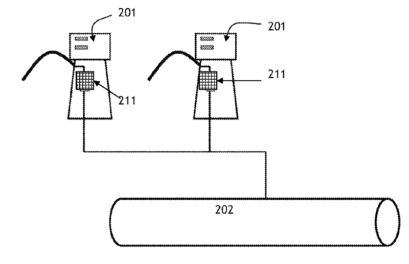
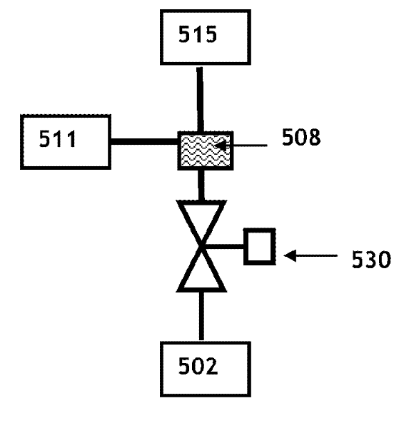
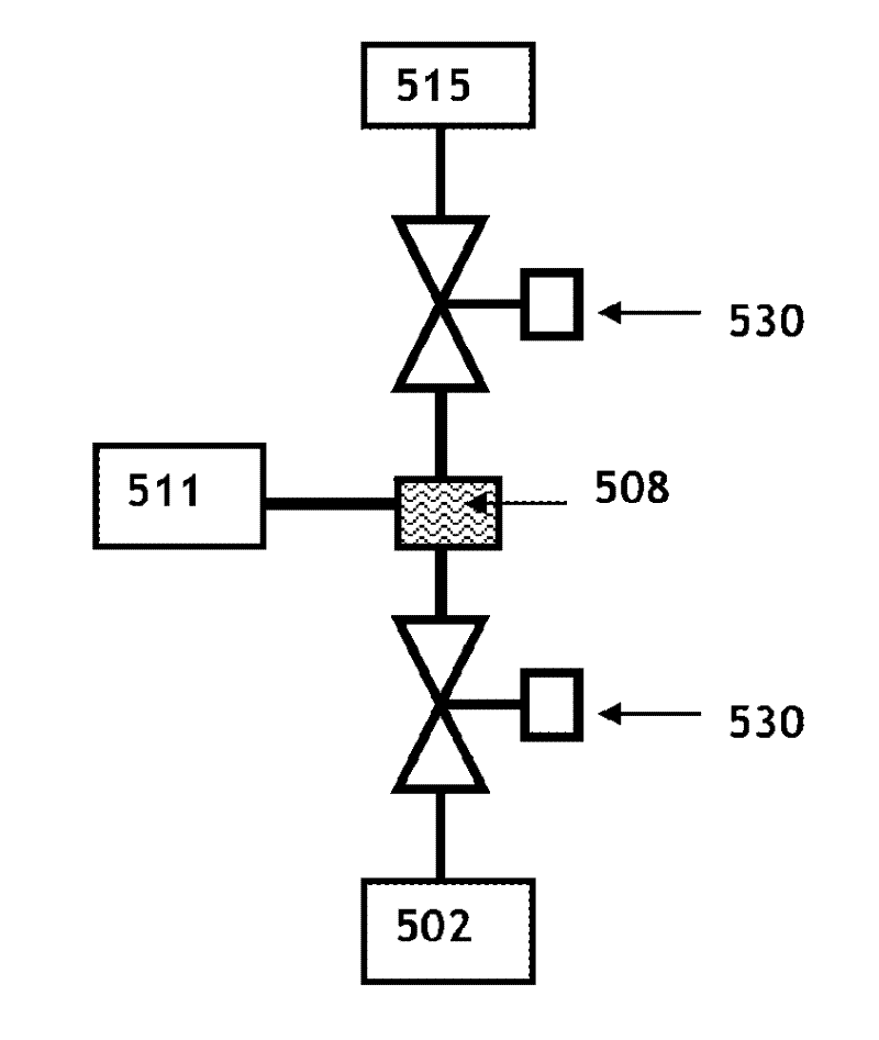
A fuel vapor management system for recovering fuel vapors displaced from vehicle fuel tanks, or the like, during the filling thereof from a bulk storage tank (102) is disclosed that has excellent emission control and pressure management. A flow splitter (108) is disclosed that utilizes positive pressure and locates downstream of a vacuum pump (111). The flow splitter is used to direct a portion of the gasoline vapors and air returned from the vehicle to an adsorbent canister (115) and the remaining portion to the UST (102), in such a proportion that a selected UST vacuum may be achieved. The flow splitter (108) may be included as a part of the vapor management system that relies upon a rapidly purging canister system and may be regenerated between vehicle refuelings, while minimizing canister volume requirements and stabilizing negative UST pressures. The disclosed system may be installed at the dispenser or centrally located.

Description

[0001] Cross References to Related Applications [0002] This formal application relies on the filing date of U.S. Provisional Application No. 61 / 104422, filed October 10, 2008, which has been filed within twelve (12) months of that filing date, incorporated by reference above The provisional application is hereby incorporated and claims priority pursuant to 35 USC 1.19(e). Background technique [0003] When fuel is pumped from the bulk storage tank into the vehicle's fuel tank or similar device, the air and vapors within the vehicle's fuel tank will be expelled during the refueling process. Exhaust vapor streams contain volatile organic compounds (VOCs), which, if released into the atmosphere, can cause ground-level ozone generation and expose humans to hazardous air pollutants (HAPs). Fueling stations based on refueling vapor control (also known as Level II control) collect these vapors and return them to an underground fuel storage tank (UST). [0004] Vacuum Assist Leve...

Claims


Application Information

Patent Timeline
IPC IPC(8): B67D7/04
CPCB67D7/0476
Inventor M.F.灿茨
Owner MEADWESTVACO CORP
Learn More