Hygienic mechanical seal flushing system for pure liquids in sanitary centrifugal pumps

a technology of mechanical seals and purified liquids, which is applied in the direction of mechanical equipment, machines/engines, liquid fuel engines, etc., can solve the problems of less effective cleaning or steamed in place, less sanitary, vibration and leakage of external piping, etc., and achieve the effect of maintaining sterility

Inactive Publication Date: 2006-09-26
WRIGHT FLOW TECH
View PDF25 Cites 25 Cited by
  • Summary
  • Abstract
  • Description
  • Claims
  • Application Information

AI Technical Summary

Benefits of technology

[0017]Another advantage of the present invention is the vertical or sloped orientation of each passage, which allows the passages to fully drain to the lowest point in the pumping chamber when the pump is not in operation. The collected liquid may then be discharged through a pumping chamber drain by use of a drain valve assembly. Thus, all “dead legs” are eliminated and sterility is maintained.
[0018]In addition, the back plate of the pump of the present invention is much thicker than is normal

Problems solved by technology

Prior art sanitary pumps with external flushing systems present a number of problems relating to the sterility of the pumps.
External piping with bends, elbows, connectors, gaskets, valves, unions, gauges, and flo

Method used


Image

  • Hygienic mechanical seal flushing system for pure liquids in sanitary centrifugal pumps
  • Hygienic mechanical seal flushing system for pure liquids in sanitary centrifugal pumps
  • Hygienic mechanical seal flushing system for pure liquids in sanitary centrifugal pumps

Examples


Embodiment Construction

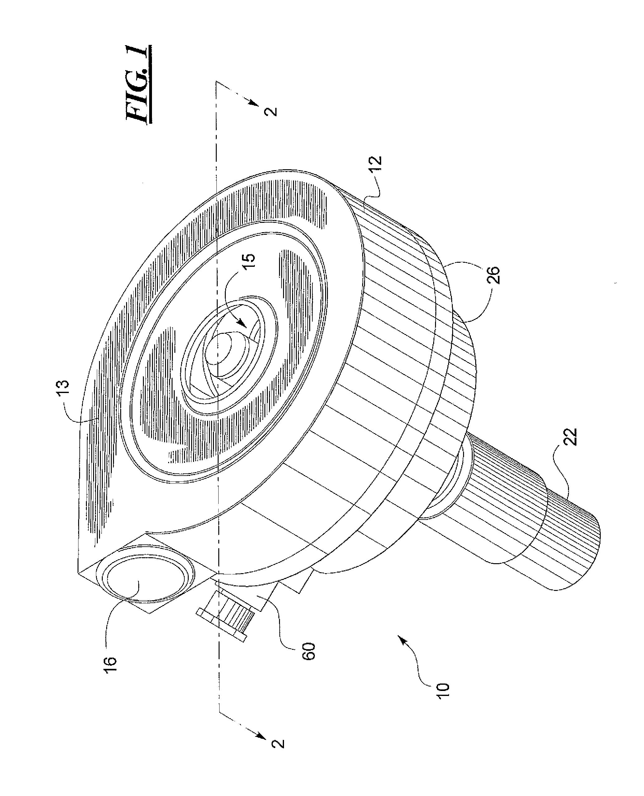
[0023]Referring now to FIG. 1, a sanitary centrifugal pump 10 constructed according to a preferred embodiment of the invention has several main components. The pump 10 includes a housing 12 having a front side 13, an inlet port 15 formed in the face of the front side 13, and an outlet port 16 formed in the side of the housing 12.

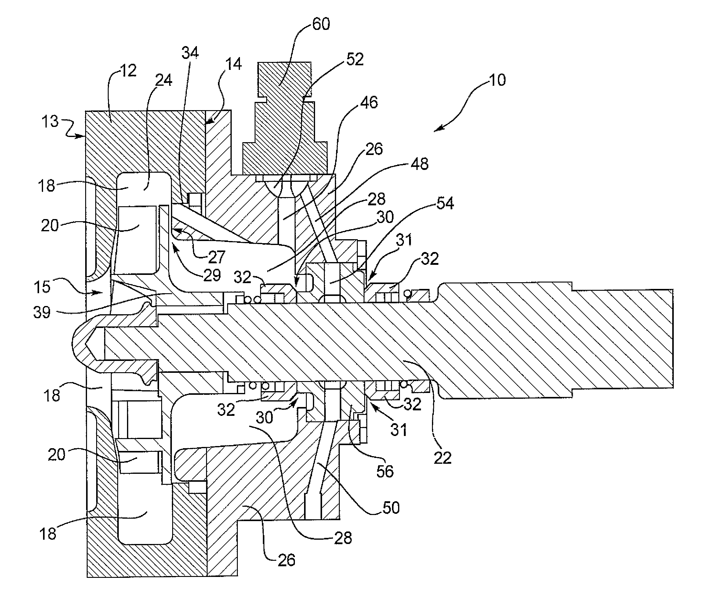
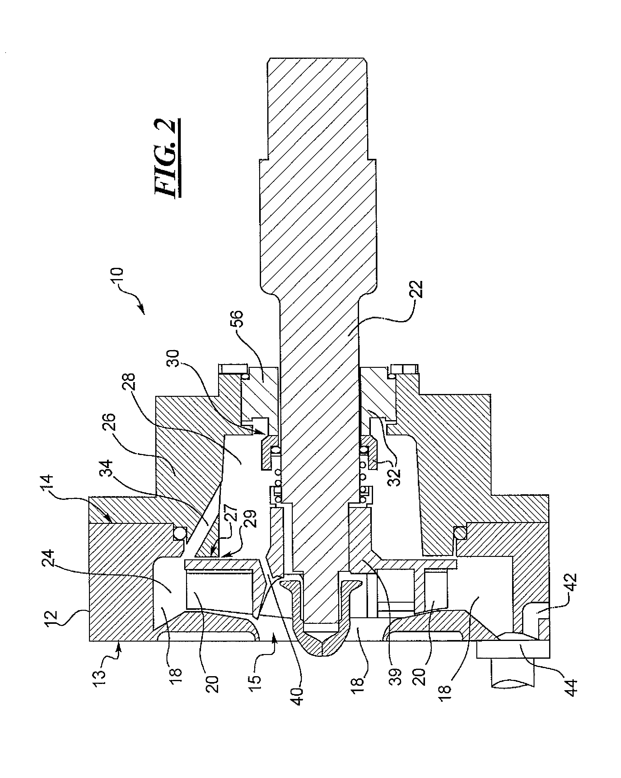
[0024]Referring to FIG. 2, the housing 12 further defines a pumping chamber 18 therein. An impeller 20, positioned within the housing 12, is connected to a shaft 22 that is mechanically coupled to a motor (not shown) and is journaled for rotation within the housing 12. A back plate 26 is fastened to a back side 14 of the housing 12 to seal the back side 14 of the housing 12. The back plate 26 defines an annular seal cavity 28 behind the impeller 20 and, with the impeller 20, defines a gap 29 between the impeller and a front wall 27 of the back plate 26. A mechanical seal 32 is at least partially positioned in the seal cavity 28 and is mounted in combination ...


PUM


Abstract

A sanitary centrifugal pump with a hygienic mechanical seal flushing system. The pump has a housing with a pumping chamber defined therein. An impeller is at least partially contained in the housing and is connected to a shaft for rotation. The rotation of the impeller creates a first liquid flow path through the pumping chamber between the inlet port and the outlet port, and the first liquid flow path creates a high pressure area in the pumping chamber. The pump includes additional seal flushing passages by which liquid is delivered to the seal cavity from the pumping chamber and returned back to the pumping chamber, to cool and flush at least a portion of the mechanical seal in the seal cavity.

Description

CROSS-REFERENCE TO RELATED APPLICATION[0001]This application is based on and claims the benefit of U.S. Provisional Patent Application Ser. No. 60 / 449,670, filed on Feb. 24, 2003.BACKGROUND OF THE INVENTION[0002]The present invention relates generally to the field of sanitary centrifugal pumps, and more particularly to a hygienic mechanical seal flushing system for pure liquids in sanitary centrifugal pumps.[0003]Sanitary centrifugal pumps are used for high purity liquids in the pharmaceutical, biotech, food, beverage and chemical industries. Of major concern in these industries are pump cleanliness and the need for continuous sterility. As a result, sanitary centrifugal pumps are typically made of stainless steel or other corrosion resistant materials, are machined instead of cast to eliminate pits, cracks, crevices and porosity, and are often polished to produce a very smooth finish. In addition, sanitary centrifugal pumps are typically part of a larger system of piping, valves, f...

Claims


Application Information

Patent Timeline
IPC IPC(8): F04D29/12F04D29/58F04D29/70
CPCF04D29/128
Inventor HOLDORF, THOMAS M.
Owner WRIGHT FLOW TECH
Why Eureka
Try Eureka