Transmission board and connector assembly made by a combination of a connector and the transmission board

a technology of transmission board and connector, which is applied in the direction of electrical discharge lamps, printed circuit aspects, coupling device connections, etc., can solve the problems of low plugging force, and achieve the effects of improving electrical characteristics, high density terminal arrangement, and high precision

Inactive Publication Date: 2006-09-26
HIROSE ELECTRIC GROUP
View PDF3 Cites 8 Cited by
  • Summary
  • Abstract
  • Description
  • Claims
  • Application Information

AI Technical Summary

Benefits of technology

[0009]Accordingly, it is an object of the invention to provide a transmission board capable of being made with high precision so as to plug to a mating connector smoothly, permitting high density terminal arrangement, and improving the electrical characteristics and a connector assembly that is made up of a connector connected to the transmission board.

Problems solved by technology

In addition, the smooth surface permits the connector terminal to slide with low friction, resulting in the low plugging force.

Method used


Image

  • Transmission board and connector assembly made by a combination of a connector and the transmission board
  • Transmission board and connector assembly made by a combination of a connector and the transmission board
  • Transmission board and connector assembly made by a combination of a connector and the transmission board

Examples


Embodiment Construction

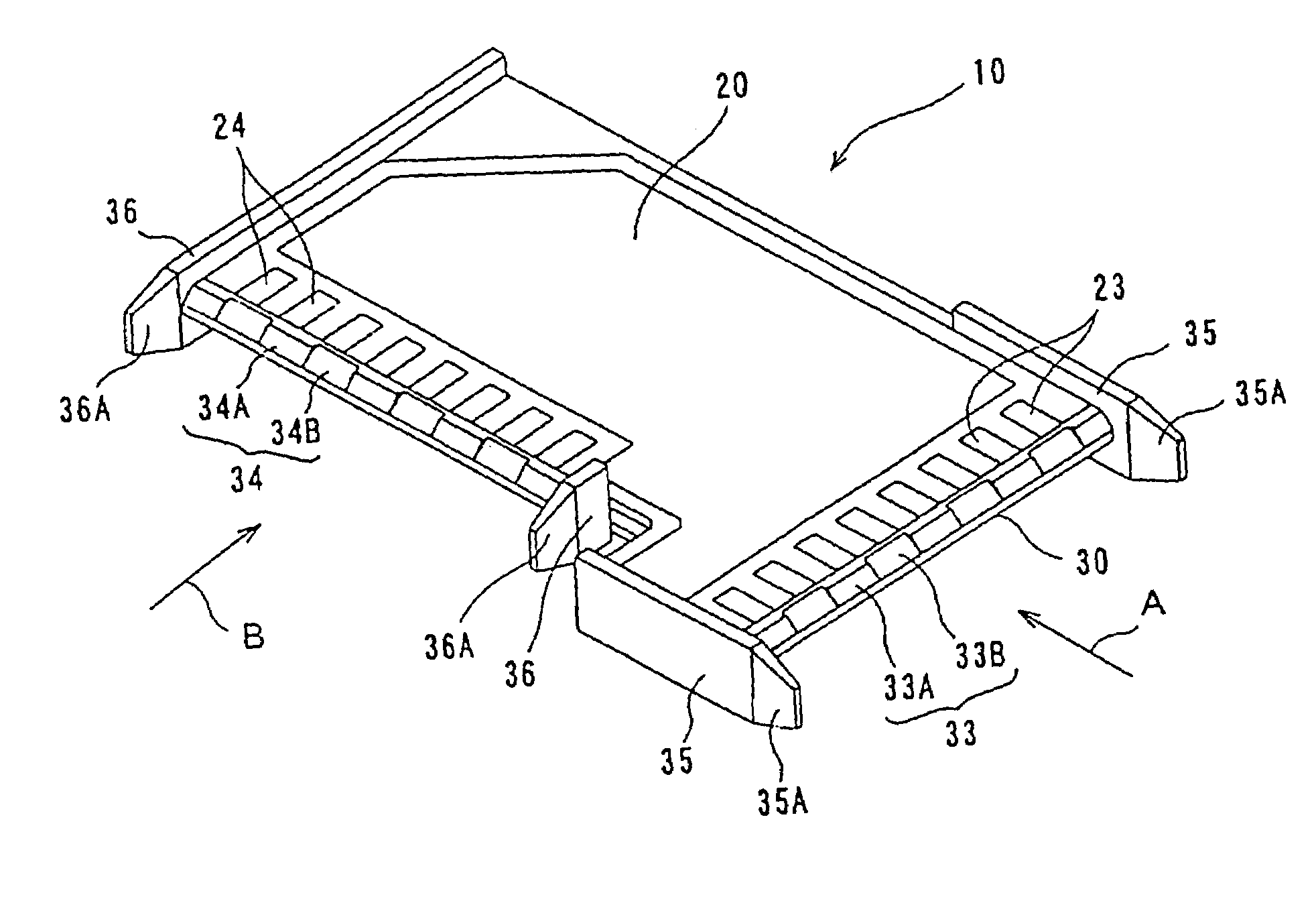
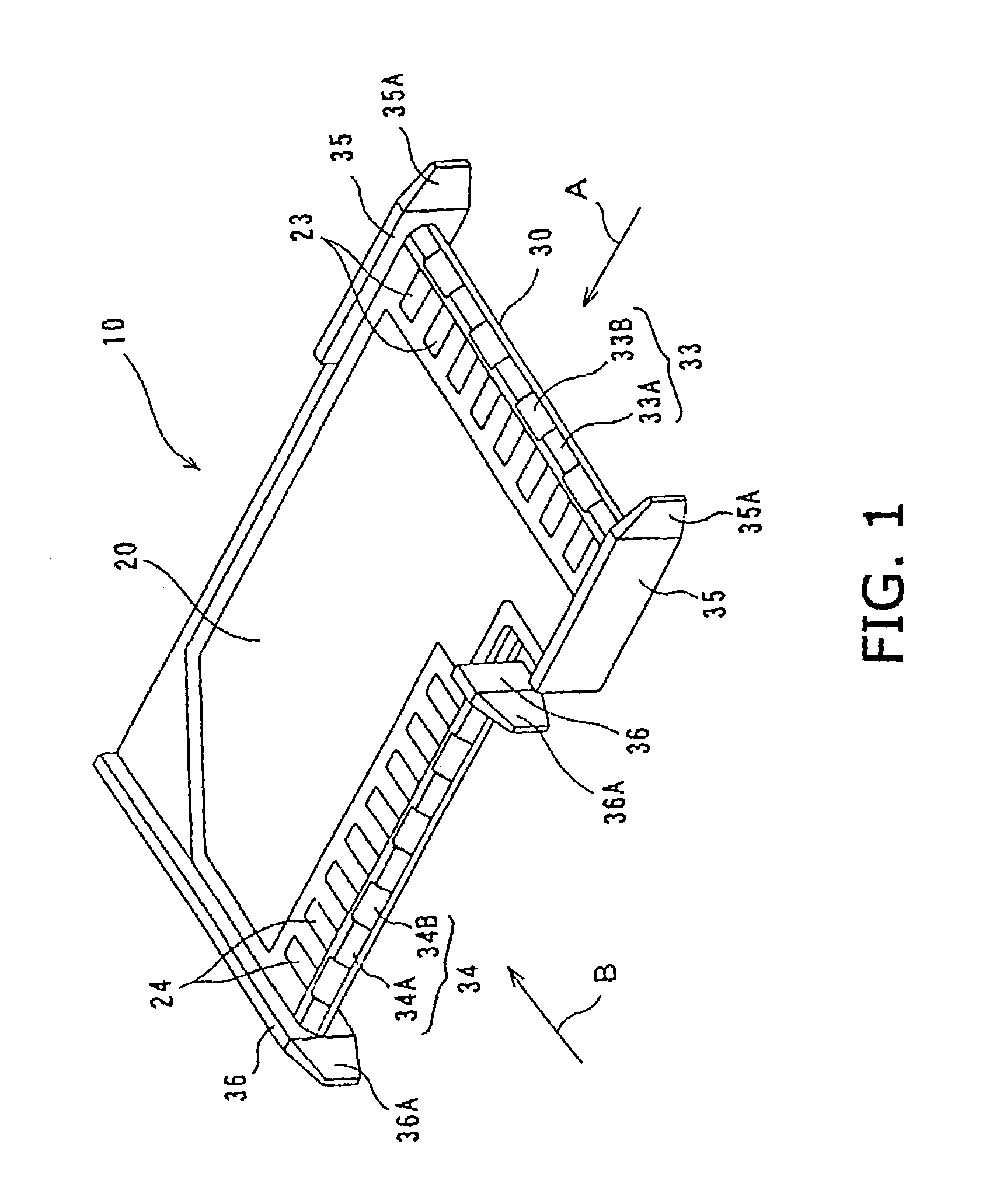
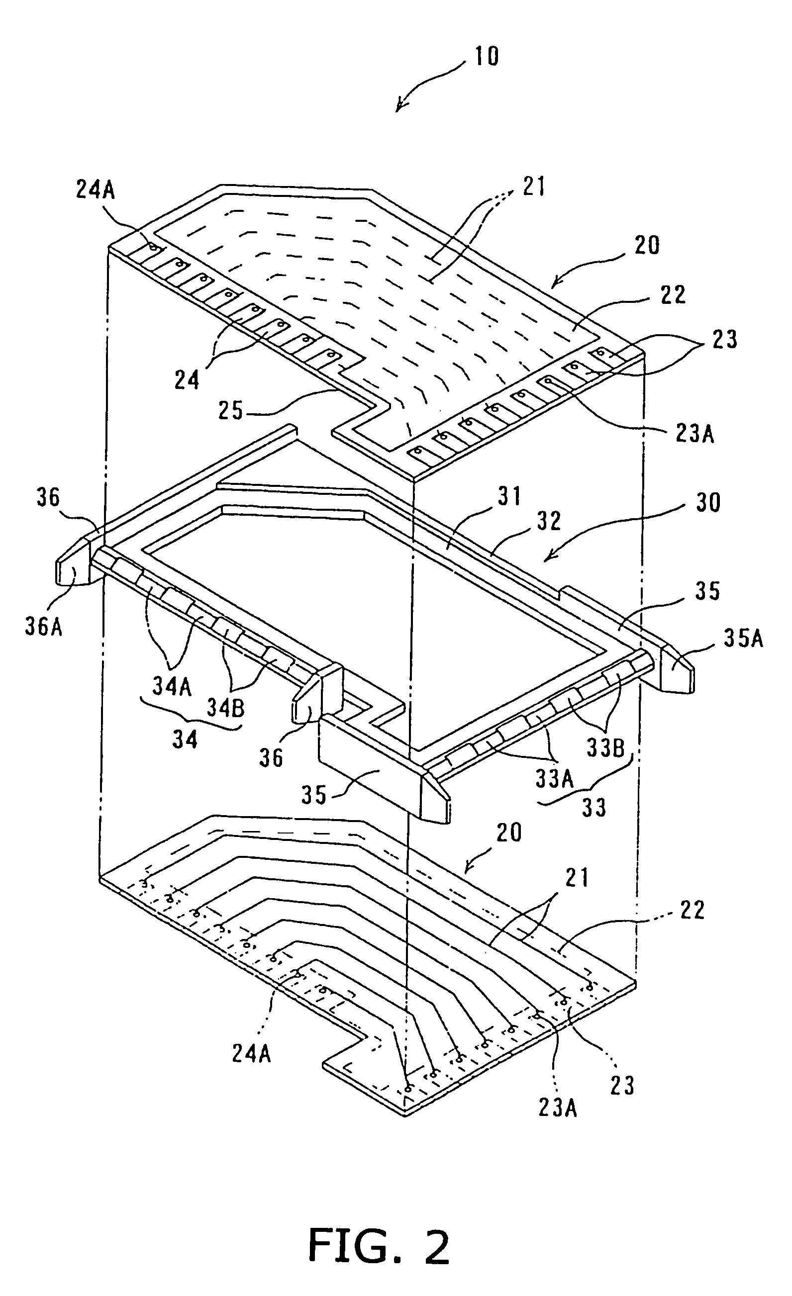
[0035]In FIGS. 1 and 2, a transmission board 10 consists of a plurality of surface boards 20 and a frame body 30. The surface boards 20 have an identical circuit and are attached to upper and lower sides of the frame body 30 such that a signal circuit 21 and a shield surface or ground circuit 22 face inside and outside, respectively. Alternatively, the surface boards 20 may have different signal circuits or only a single surface board 20 may be used.

[0036]The surface board 20 has a plurality of signal circuits 21 on a surface thereof and the ground circuit 22 on the other surface. The shield surface 22 covers almost all the signal circuits 21. Connection pads 23 and 24 are provided on adjacent two edges of the surface board 20 on the side of the shield face 22. The number of connection pads 23 or 24 is the same as that of the signal circuits 21 In FIG. 2, the connection terminals or pads 23 and 24 are provided at one and the other end of each linear signal circuit 21. A conductive p...


PUM


Abstract

A transmission board (10) comprises a frame body (30) and a surface board (20) supported by the frame body (30) and having a transmission circuit. The frame body (30) has plugging edges (33, 34) that project from the edges of the surface board (20) for guiding the terminals of mating connectors to connection pads on the surface board (20). The plugging edges have guiding slopes 33A and 33B, and 34A and 34B. At least the plugging edges of the frame body (30) are made of a metal or resin molding.

Description

BACKGROUND OF THE INVENTION[0001]1. Field of the Invention[0002]The present invention relates to a transmission board having a transmission circuit on a surface thereof and connection pads on the surface edge for connection with a mating connector and a connector assembly consisting of a connector connected to the transmission board.[0003]2. Description of the Related Art[0004]Generally, a transmission board includes a resinous circuit board with transmission circuit or circuits printed on one or both sides thereof and connection pads provided on an edge of the circuit board for connection with a mating connector. Such a transmission board is disclosed in U.S. Pat. No. 6,171,115; FIGS. 1–2. The edge of the circuit board is tapered so as to facilitate connection between the connection pads and the spring contacts of terminals for a mating connector. The tapered edge is made by planomilling.[0005]The above circuit board, however, has the following disadvantages.[0006]First of all, the...

Claims


Application Information

Patent Timeline
Patent Type & Authority Patents(United States)
IPC IPC(8): H01R24/00H02G3/16H05K1/11H05K1/14
CPCH05K1/117H01R12/722H05K1/144H05K2201/2027H05K2201/09154
Inventor MATSUO, TSUTOMUNAGATA, MASAKAZU
Owner HIROSE ELECTRIC GROUP
Why Eureka
Try Eureka