
Method to increase bump height and achieve robust bump structure

a bump structure and bump technology, applied in the direction of semiconductor devices, semiconductor/solid-state device details, electrical apparatus, etc., can solve the problems of reducing circuit resistance, affecting electrical performance, and low potential failure points

Inactive Publication Date: 2006-09-26
TAIWAN SEMICON MFG CO LTD
View PDF5 Cites 25 Cited by
  • Summary
  • Abstract
  • Description
  • Claims
  • Application Information

AI Technical Summary

Problems solved by technology

Packages with fewer interconnecting links lower potential failure points, reduce the circuit resistance, and reduce interconnect capacitance, which affects electrical performance.
The large solder bump diameter becomes a disadvantage in the manufacture of fine pitch bumping due to the concerns of solder bump bridging leading to short circuit in the integrated circuit.
The sharp angle degrades the solder bump joint integrity and reliability and consequently, more bump protection is needed in flip chip packaging.

Method used


Image

  • Method to increase bump height and achieve robust bump structure
  • Method to increase bump height and achieve robust bump structure
  • Method to increase bump height and achieve robust bump structure

Examples


Embodiment Construction

[0012]In the following description, numerous specific details are set forth to provide a thorough understanding of the present invention. However, one having an ordinary skill in the art will recognize that the invention can be practiced without these specific details. In some instances, well-known structures and processes have not been described in detail to avoid unnecessarily obscuring the present invention.

[0013]Reference will now be made in detail to the present preferred embodiments of the present invention, examples of which are illustrated in the accompanying drawings.

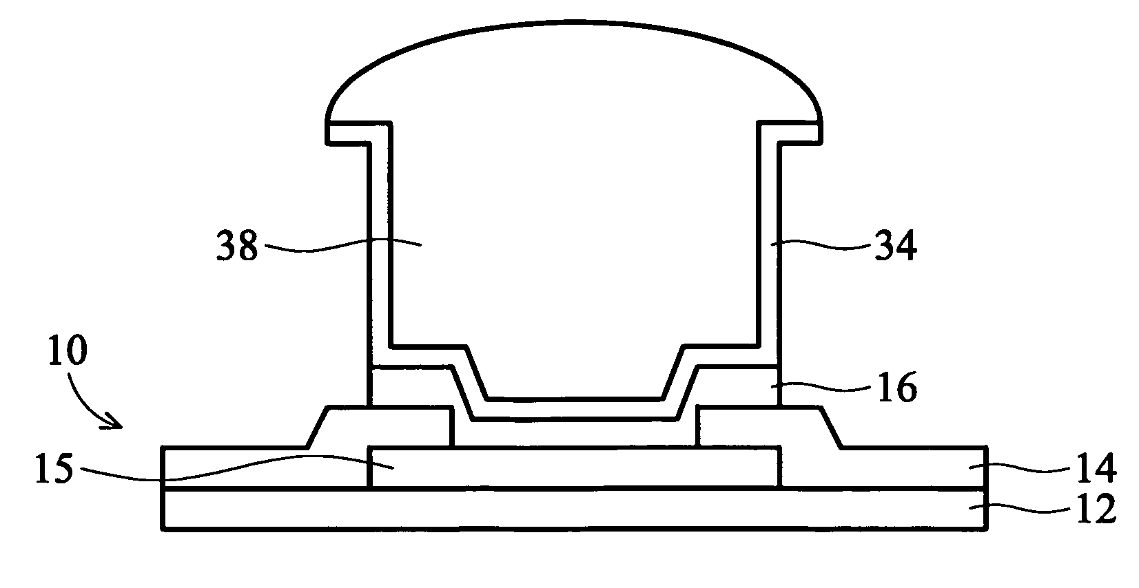
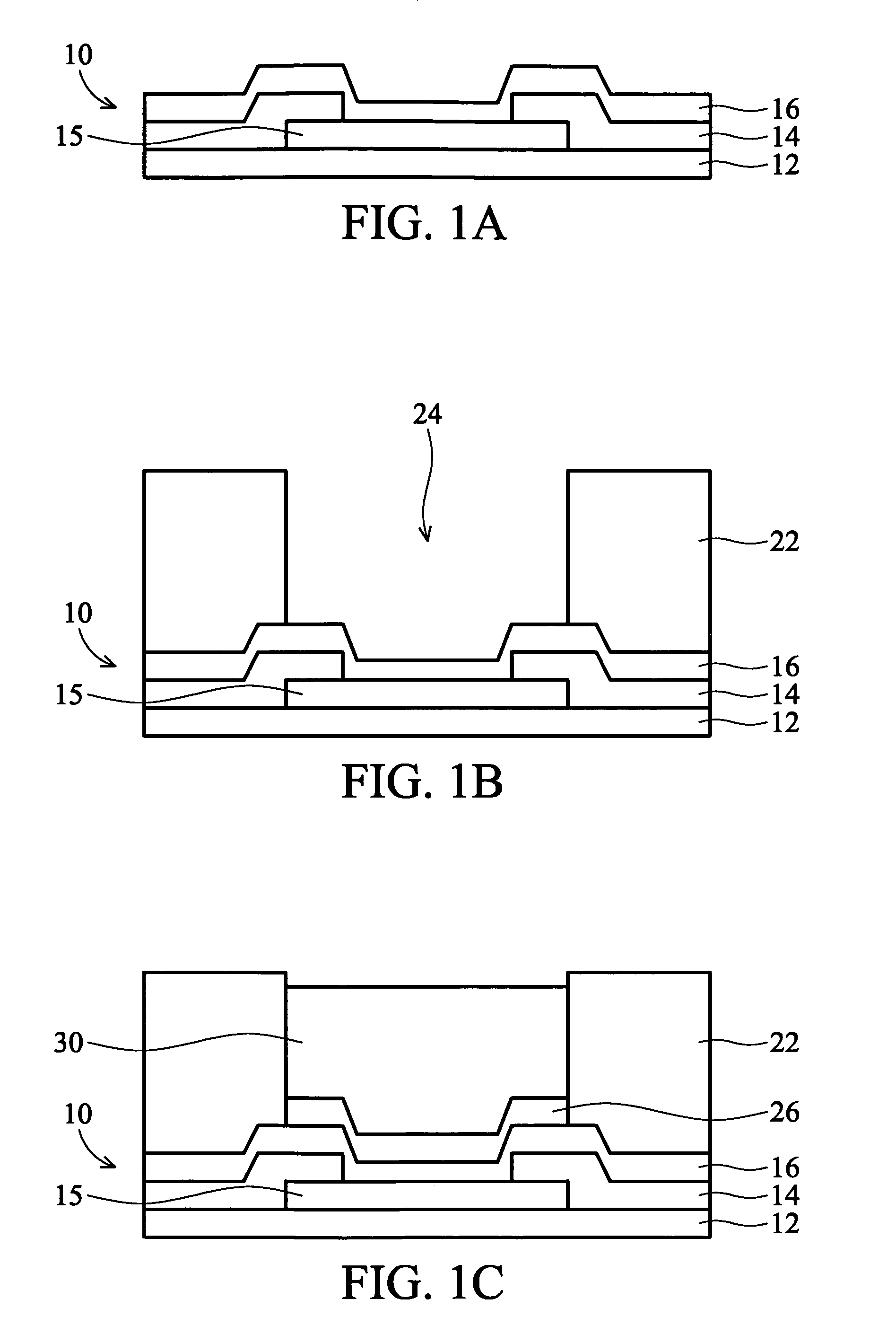
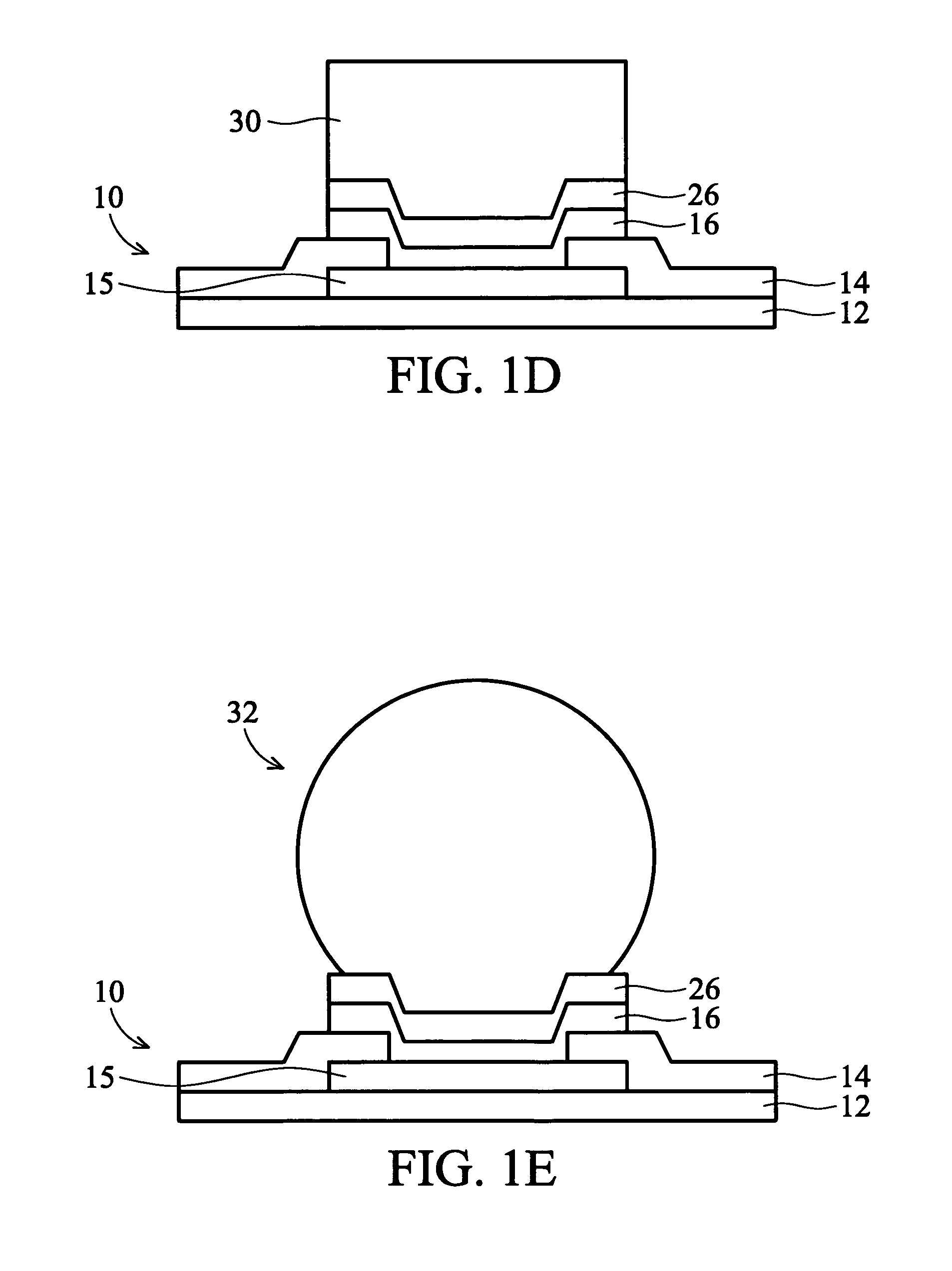
[0014]As shown in FIG. 2A, a cross-sectional view of a semiconductor device depicting a method of forming a solder bump structure according to one embodiment of the present invention is provided. A semiconductor wafer 10 is provided having a base semiconductor substrate 12 with metal interconnect layers (not shown) overlying substrate 12 and a passivation layer 14, which may be one or more layers, that extends ...


PUM


Abstract

Methods for forming solder bumps on a semiconductor device are provided. In one embodiment, a substrate is provided having at least one contact pad formed thereon. A passivation layer is formed overlying the substrate, the passivation layer having at least one opening therein exposing a portion of the contact pad. A UBM (Under Bump Metallurgy) layer is formed overlying the passivation layer and the contact pad. A patterned and etched light sensitive layer is provided overlying the UBM layer, the light sensitive layer defining at least one opening therein. A sidewall bump layer is formed over the exposed surfaces of the light sensitive layer and the UBM layer. A portion of the sidewall bump layer above the light sensitive layer is removed. A solder material is deposited in the opening bordered by the etched sidewall bump layer to form a solder column. The solder column is then reflown to create a solder bump.

Description

BACKGROUND[0001]The present invention relates generally to the formation of solder bumps on an integrated circuit device, and more particularly, to the formation of solder bumps having improved height and reliability.[0002]Faster, reliable, and higher-density circuits at lower costs are the goals for integrated circuit (IC) packaging. Conventional wirebond technology, the most common method for electrically connecting aluminum bonding pads on a chip surface to the package inner lead terminals on the lead-frame or substrate has proven to be low cost and reliable. But for the future, packaging goals will be met by increasing the density of chips and reducing the number of internal interconnections. Packages with fewer interconnecting links lower potential failure points, reduce the circuit resistance, and reduce interconnect capacitance, which affects electrical performance. The need to reduce the IC package to fit end-user applications (e.g., smart cards, palmtop computers, camcorder...

Claims


Application Information

Patent Timeline
Patent Type & Authority Patents(United States)
IPC IPC(8): H01L21/44
CPCH01L24/03H01L24/05H01L2924/01033H01L24/11H01L2224/03912H01L2224/0401H01L2224/05082H01L2224/05558H01L2224/05624H01L2224/05647H01L2224/1147H01L2224/11901H01L2224/11912H01L2924/01013H01L2924/01014H01L2924/01022H01L2924/01028H01L2924/01029H01L2924/0105H01L2924/01078H01L2924/01082H01L2924/014H01L2924/05042H01L2924/14H01L2924/30105
Inventor TSAO, PEI-HAWCHAO, CLINTONWANG, CHUNG-YU
Owner TAIWAN SEMICON MFG CO LTD
Learn More