NMR measurement method

a measurement method and nmr technology, applied in the direction of magnetic measurement, measurement devices, instruments, etc., can solve the problems of low-temperature cooled nmr probes, limited cooling capability, and inability to maintain low temperatur

Inactive Publication Date: 2006-09-26
JEOL RESONANCE
View PDF13 Cites 6 Cited by
  • Summary
  • Abstract
  • Description
  • Claims
  • Application Information

AI Technical Summary

Benefits of technology

[0043]In a still additional feature of the present invention, the RF power of the frequency not affecting the measurement of the NMR signal can be so adjusted that the ratio of the RF power reflected from the detection coil or the RF irradiation coil to the RF power applied to the detection coil or the RF irradiation coil is minimized.
[0049]In a still additional feature of the present invention, the RF power applied from the second RF power application means can be adjusted based on the value of the power meter such that the reflected RF power is minimized.

Problems solved by technology

The prior art low-temperature cooled NMR probe has one problem.
However, the cooling capability is limited.
Consequently, the low temperature can no longer be maintained.
As a result, RF magnetic fields of desired intensity cannot be produced within the detection coil.
This problem produces an adverse effect during reception of an NMR signal, as well as during excitation of nuclear spins.
Hence, normal NMR signals cannot be obtained.
The similar problem will also occur at the provided RF irradiation coils.

Method used


Image

  • NMR measurement method
  • NMR measurement method
  • NMR measurement method

Examples


Embodiment Construction

[0065]The preferred embodiments of the present invention are hereinafter described with reference to the accompanying drawings. FIGS. 6(a) and 6(b) show an NMR apparatus according to one embodiment of the present invention. FIG. 6(a) is a circuit diagram, and FIG. 6(b) shows the relation between the NMR probe and the spectrometer.

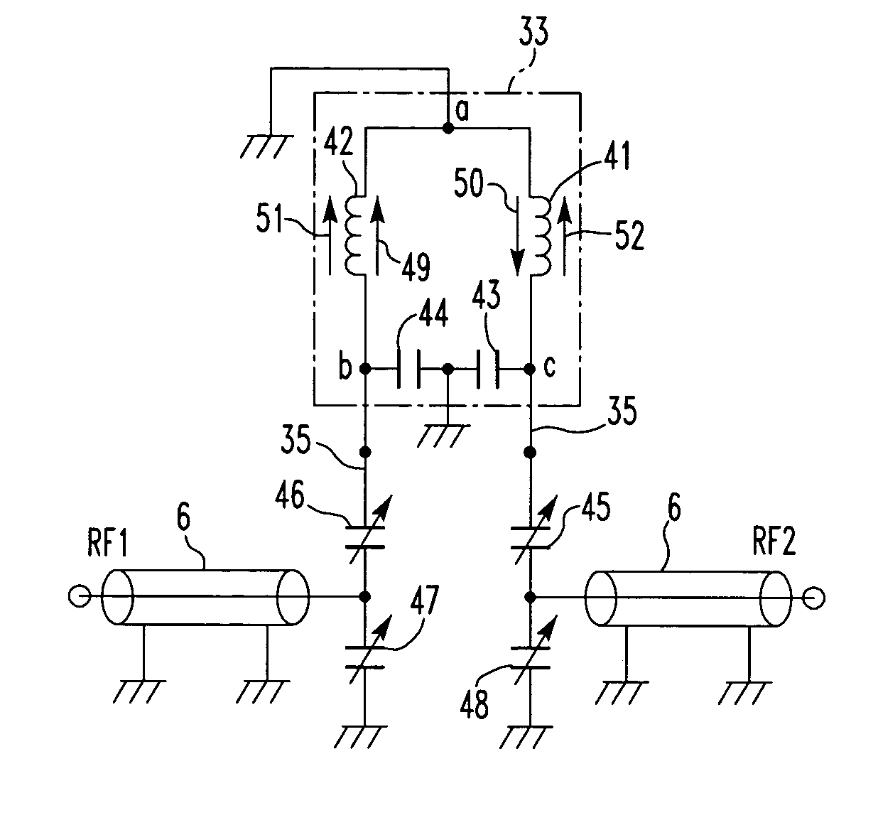
[0066]The apparatus has an NMR detection coil 33. Where the coil 33 is of the saddle-type as shown in FIGS. 4(a)–4(d), a cylindrical winged portion of coil foil 37, a coil bobbin 32 made of a cylindrical dielectric, and a cylindrical conductor 39 in the form of a cylindrical band form two capacitors 43 and 44 as shown in FIG. 6(a). A cylindrical annular portion of the coil foil 37 and two vertical band portions form two inductors 41 and 42, thus forming an LC resonator capable of resonating with RF signals.

[0067]A first tuning-and-matching circuit for matching to a first RF frequency RF1 necessary for measurement of NMR signals and a second tuning-and-match...


PUM


Abstract

There is disclosed an NMR measurement method and NMR apparatus in which the temperature of the NMR detection coil or the RF irradiation coil hardly varies if pulsed RF power is applied to the coil during NMR measurements. The apparatus includes the detection coil or the RF irradiation coil, a first RF power application means for applying RF power of a frequency necessary for measurement of NMR signals, a second RF power application means for applying RF power of a frequency not affecting the measurement of NMR signals, and a control means for controlling the two power application means such that the sum of the RF power applied to the coil from the first application means and the RF power applied to the coil from the second application means is kept almost constant.

Description

BACKGROUND OF THE INVENTION[0001]1. Field of the Invention[0002]The present invention relates to an NMR measurement method and NMR apparatus and, more particularly, to an NMR measurement method and NMR apparatus using a detector assembly that is cooled to a cryogenic temperature by low-temperature helium gas to thereby enhance the sensitivity with which NMR signals are detected.[0003]2. Description of Related Art[0004]In an NMR apparatus, a strong static magnetic field is applied to a sample to induce a precessional motion of the magnetic moment of each atomic nucleus having a nuclear spin within the sample about the direction of the static field. Under this condition, an RF magnetic field is applied perpendicularly to the direction of the static field to induce a precessional motion of the magnetic moment of the atomic nucleus. Then, an NMR signal released when the precessional motion of the magnetic moment of the atomic nucleus returns to ground state from an excited state is obse...

Claims


Application Information

Patent Timeline
Patent Type & Authority Patents(United States)
IPC IPC(8): G01V3/00G01R33/34G01R33/36
CPCG01R33/31G01R33/3403G01R33/3635G01R33/34076G01R33/34069G01R33/34023G01R33/34092
Inventor HASEGAWA, KENICHIMIZUNO, KENTAROUANAI, TAKAHIRO
Owner JEOL RESONANCE
Why Eureka
Try Eureka