Disk drive comprising a spindle motor having a windings shield for reduced disk voltage coupling

Active Publication Date: 2006-09-26
WESTERN DIGITAL TECH INC
View PDF20 Cites 125 Cited by
  • Summary
  • Abstract
  • Description
  • Claims
  • Application Information

AI Technical Summary

Benefits of technology

[0012]The present invention may also be regarded as a spindle motor for rotating a disk in a disk drive. The disk drive comprising a head actuated over a surface of the disk. The spindle motor comprises a base, a shaft coupled to the base, and a ring-shaped stator having a planar alignment substantially parallel with the disk wherein the shaft is disposed axially through the ring-shaped stator. The ring-shaped stator comprises a plurality of stator teeth, wherein a winding is wound around each stator tooth. When the windings are energized, a voltage emanati

Problems solved by technology

The windings of the spindle motor within a disk drive induce a voltage which can couple to the surface of the spinning disk an

Method used


Image

  • Disk drive comprising a spindle motor having a windings shield for reduced disk voltage coupling
  • Disk drive comprising a spindle motor having a windings shield for reduced disk voltage coupling
  • Disk drive comprising a spindle motor having a windings shield for reduced disk voltage coupling

Examples


Embodiment Construction

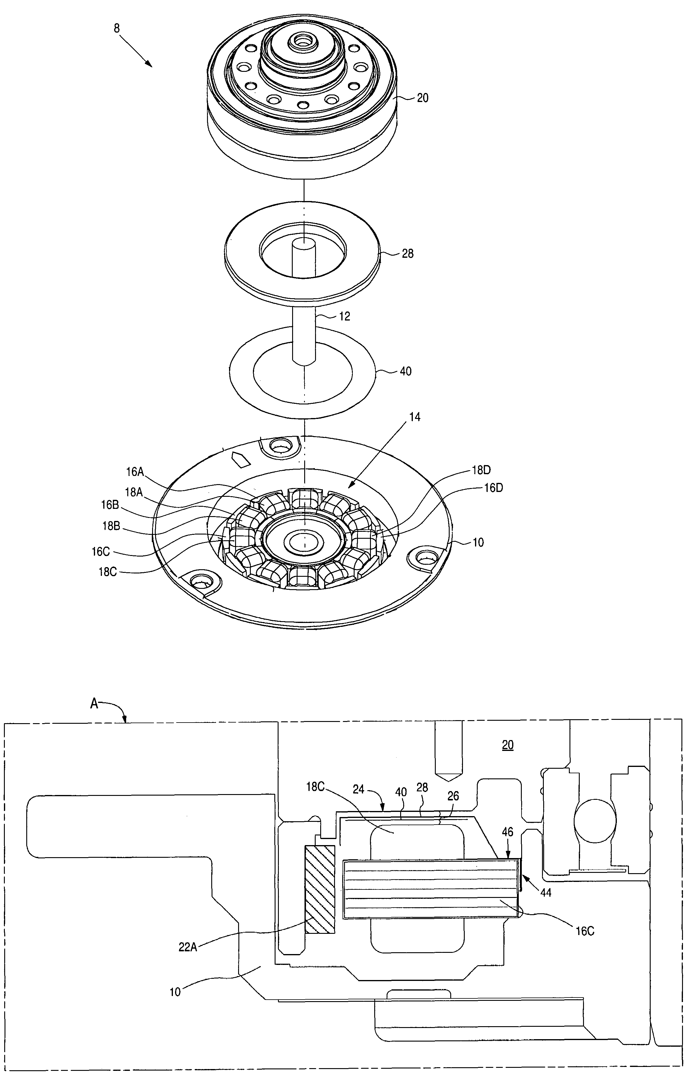
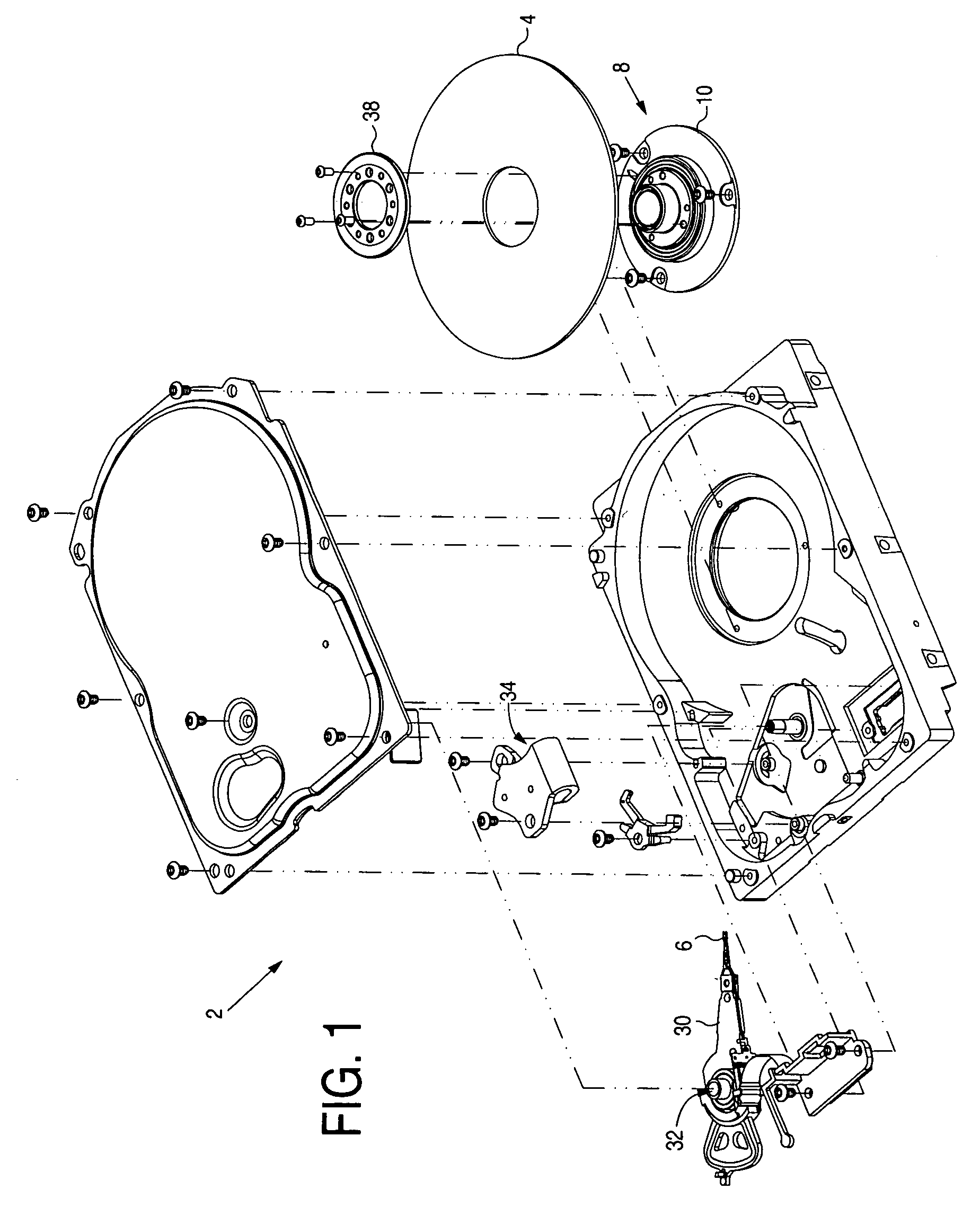
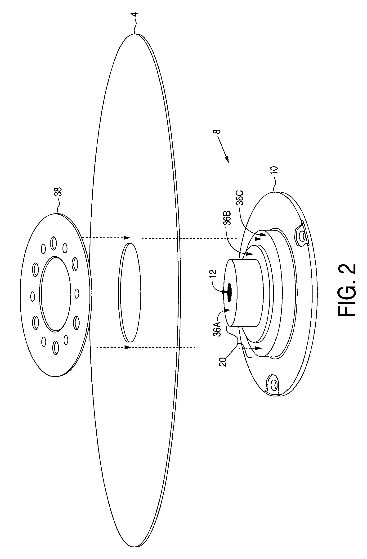
[0022]FIG. 1 shows an exploded view of a disk drive 2 according to an embodiment of the present invention comprising a disk 4, a head 6 actuated over a surface of the disk 4, and a spindle motor 8 for rotating the disk 4. An example embodiment of the spindle motor 8 shown in the exploded view of FIG. 3A comprises a base 10, a shaft 12 coupled to the base 10, and a ring-shaped stator 14 having a planar alignment substantially parallel with the disk 4. The shaft 12 is disposed axially through the ring-shaped stator 14. The ring-shaped stator 14 comprises a plurality of stator teeth (e.g., 16A–16D), wherein a winding (e.g., 18A–18D) is wound around each stator tooth. When the windings (e.g., 18A–18D) are energized, a voltage emanating from the windings (e.g., 18A–18D) being at least partially coupled to the surface of the disk 4. The spindle motor 8 further comprises a hub 20 comprising a plurality of magnets (e.g., 22A and 22B of FIG. 5A) for interacting with the stator teeth (e.g., 1...


PUM


Abstract

A disk drive is disclosed comprising a disk, a head actuated over a surface of the disk, and a spindle motor for rotating the disk. The spindle motor comprises a ring-shaped stator having a plurality of stator teeth each wound with a winding. The spindle motor further comprises a hub having a plurality of magnets for interacting with the stator teeth to rotate the hub about the shaft when the windings are energized. A ring-shaped shield is disposed in a vertical gap between the windings and the hub to reduce a voltage coupled from the windings to the surface of the disk.

Description

BACKGROUND OF THE INVENTION[0001]1. Field of the Invention[0002]The present invention relates to disk drives. More particularly, the present invention relates to a disk drive comprising a spindle motor having a windings shield for reduced disk voltage coupling.[0003]2. Description of the Prior Art[0004]The windings of the spindle motor within a disk drive induce a voltage which can couple to the surface of the spinning disk and damage magnetoresistive (MR) heads, particularly as the heads shrink in size and become even more sensitive to disk voltages. U.S. patent application Ser. No. 09 / 865,240 discloses a disk drive which grounds the spindle motor stator to the shaft and / or the base which reduces the disk voltage coupling from the windings of the spindle motor. However, further reduction in the disk voltage coupling is desirable.SUMMARY OF THE INVENTION[0005]The present invention may be regarded as a disk drive comprising a disk, a head actuated over a surface of the disk, and a sp...

Claims


Application Information

Patent Timeline
IPC IPC(8): G11B19/20
CPCG11B19/2009H02K21/22H02K1/146H02K1/187H02K5/1732H02K11/0141H02K11/014H02K1/2791
Inventor RYAN, ROBERT P.RICE, ALAN P.JACOBY, JON E.
Owner WESTERN DIGITAL TECH INC
Why Eureka
Try Eureka