PICA system detector calibration

a detector and detector technology, applied in the field of detector signal calibration, can solve the problems of time-consuming fault localization methods using beam probe systems, easy perturbation of devices, slow design process, etc., and achieve the effect of less intensity gradients

Inactive Publication Date: 2006-09-26
DCG SYST
View PDF15 Cites 10 Cited by
  • Summary
  • Abstract
  • Description
  • Claims
  • Application Information

AI Technical Summary

Problems solved by technology

New package types, shrinking process geometries and new materials pose challenges for gathering vital data during the integrated circuit (IC) design debug and validation process.
Increasingly sensitive devices are easily perturbed during probing, which skews results and slows the design process.
Fault localization methods using beam probe systems are time-consuming even with access to IC layout knowledge since each node must be probed serially to trace the location of a faulty circuit element.
Tester and other equipment time is often limited, forcing design debug experts to extract timing measurements from the device one probing session at a time, often adding weeks to the debug and verification cycle.
Data acquisition and analysis can be a development bottleneck.
Devices manufactured with 0.13-micron geometry have critical signal nodes so small and numerous that the acquisition process is too time-consuming for efficient probe by serial, beam-based instruments.
Other interpolation algorithms considered in the prior art were rejected because they are slower (bicubic) or less flexible (interpolation by pixel line).
A disadvantage of the prior art calibration described above is that the correction matrix produces a corrected PICA image having undesirable and troublesome discontinuities.

Method used


Image

  • PICA system detector calibration
  • PICA system detector calibration
  • PICA system detector calibration

Examples


first embodiment

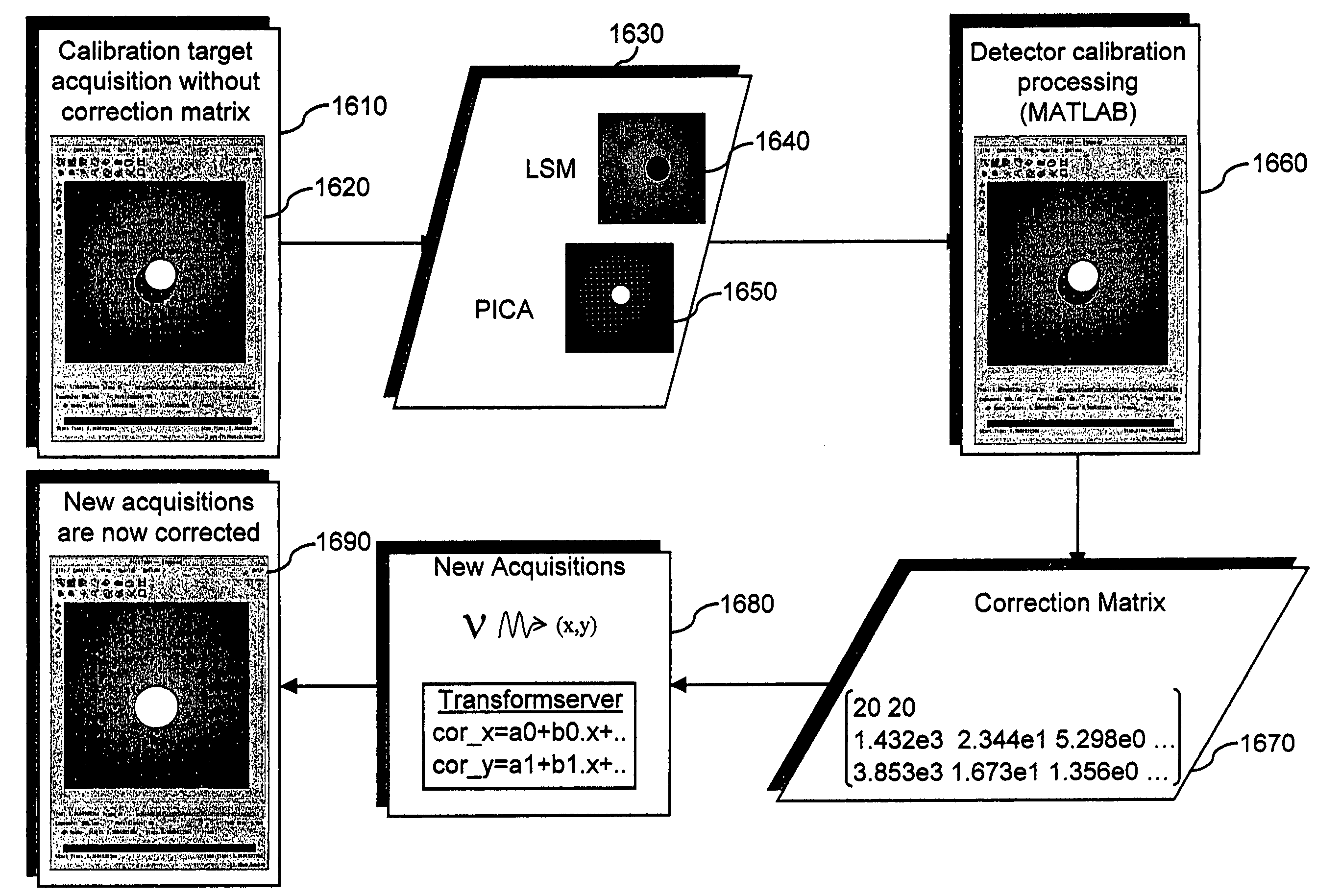
[0071]Computing correction coefficients in accordance with embodiments of the invention will now be described. A first embodiment is based on a local correction: coefficients are found for a bilinear equation that gives the transformation of a rectangle formed by four blobs in the PICA image to fit its associated rectangle in the LSM image. An extrapolation of these coefficients for the rectangles at the outer edges of the image is done where there is no identified blob in the PICA image. For the matching rectangle in the emission image, if there are M points inside this rectangle, the corrected coordinates (cx,cy) for the nth point can be expressed in function of the observed coordinates (x,y) using the following equations:

[0072]cxn=ai0+ai1⁢xn+ai2⁢yn+ai3⁢xn⁢yncyn=bi0+bi1⁢xn+bi2⁢yn+bi3⁢xn⁢yn⁢⁢for⁢⁢n=1,M

[0073]As the corrected coordinates are in fact the coordinates in the LSM image, the system above can be resolved and the (aij, bij) coefficients found for each rectangle are stored i...

second embodiment

[0075]A second embodiment for computing correction coefficients is based on a global correction. Global transformations impose a single mapping function on the whole image. The general model for characterizing misregistration between two images is a pair of bivariate polynomials. The coefficients of the polynomials are adjusted using all the matching blobs in both images. Polynomials of degree one or more can be used.

[0076]Polynomials of degree one are sufficient for correcting shift or rotation, but is not adequate for correcting distortion. Polynomials of degree two are sufficient to model most of the usual deformations such as scale, shift and rotation. Polynomials of degree three or more will correct for distortion, though degree four or more has been found to introduce noise. This method avoids the need for extrapolation anymore and is much less time-consuming.

[0077]The corrected coordinates are linked with the observed ones by the following polynomial equations:

[0078]cx=∑p=0N⁢...


PUM


Abstract

Methods, apparatus and data structures useful in correcting PICA image data are described. An exemplary method comprises acquiring optical image data of a target having identifiable optical-image features, acquiring PICA image data of the target having identifiable PICA-image features corresponding to the optical-image features, matching PICA-image features with corresponding optical-image features, and calculating from matched PICA-image features and optical-image features a set of coefficients defining relationships between observed positions of PICA-image features and optical-image features. Corrections are applied to the observed positions of detected photons based on the coefficients. The coefficients may provide a local correction using a bilinear relationship giving the transformation of a rectangle formed by four features of the PICA-image data to fit a corresponding rectangle in the optical-image data. Alternatively, the coefficients may provide a global mapping function defining transformation of any point of the PICA-image data to fit a corresponding point in the optical-image data.

Description

BACKGROUND[0001]1. Field of the Invention[0002]The present invention relates to calibration of detector signals in PICA (picosecond imaging circuit analysis) systems, and particularly to methods, apparatus and data structures useful for calibration of detector signals in PICA systems.[0003]2. Prior Art[0004]New package types, shrinking process geometries and new materials pose challenges for gathering vital data during the integrated circuit (IC) design debug and validation process. Increasingly sensitive devices are easily perturbed during probing, which skews results and slows the design process.[0005]Fault localization methods using beam probe systems are time-consuming even with access to IC layout knowledge since each node must be probed serially to trace the location of a faulty circuit element. Tester and other equipment time is often limited, forcing design debug experts to extract timing measurements from the device one probing session at a time, often adding weeks to the d...

Claims


Application Information

Patent Timeline
Patent Type & Authority Patents(United States)
IPC IPC(8): G06K9/00G01R31/311G01R35/00
CPCG01R31/311G01R35/00
Inventor DAJEE, GIRISHLE COUPANEC, PATRICIALEIBOWITZ, MARTIN D.
Owner DCG SYST
Why Eureka
Try Eureka