Fault forwarding in an optical network

a technology of optical network and fault forwarding, which is applied in the direction of frequency-division multiplex, transmission monitoring, instruments, etc., can solve the problems of network performance being deleteriously affected, services not having standard alarm signal protocols

Inactive Publication Date: 2006-09-26
CIENA
View PDF4 Cites 32 Cited by
  • Summary
  • Abstract
  • Description
  • Claims
  • Application Information

AI Technical Summary

Problems solved by technology

However, some types of services do not have standard alarm signal protocols comparable to the AIS or MS-AIS.
Consequently, network performance may be deleteriously affected.

Method used


Image

  • Fault forwarding in an optical network
  • Fault forwarding in an optical network
  • Fault forwarding in an optical network

Examples


Embodiment Construction

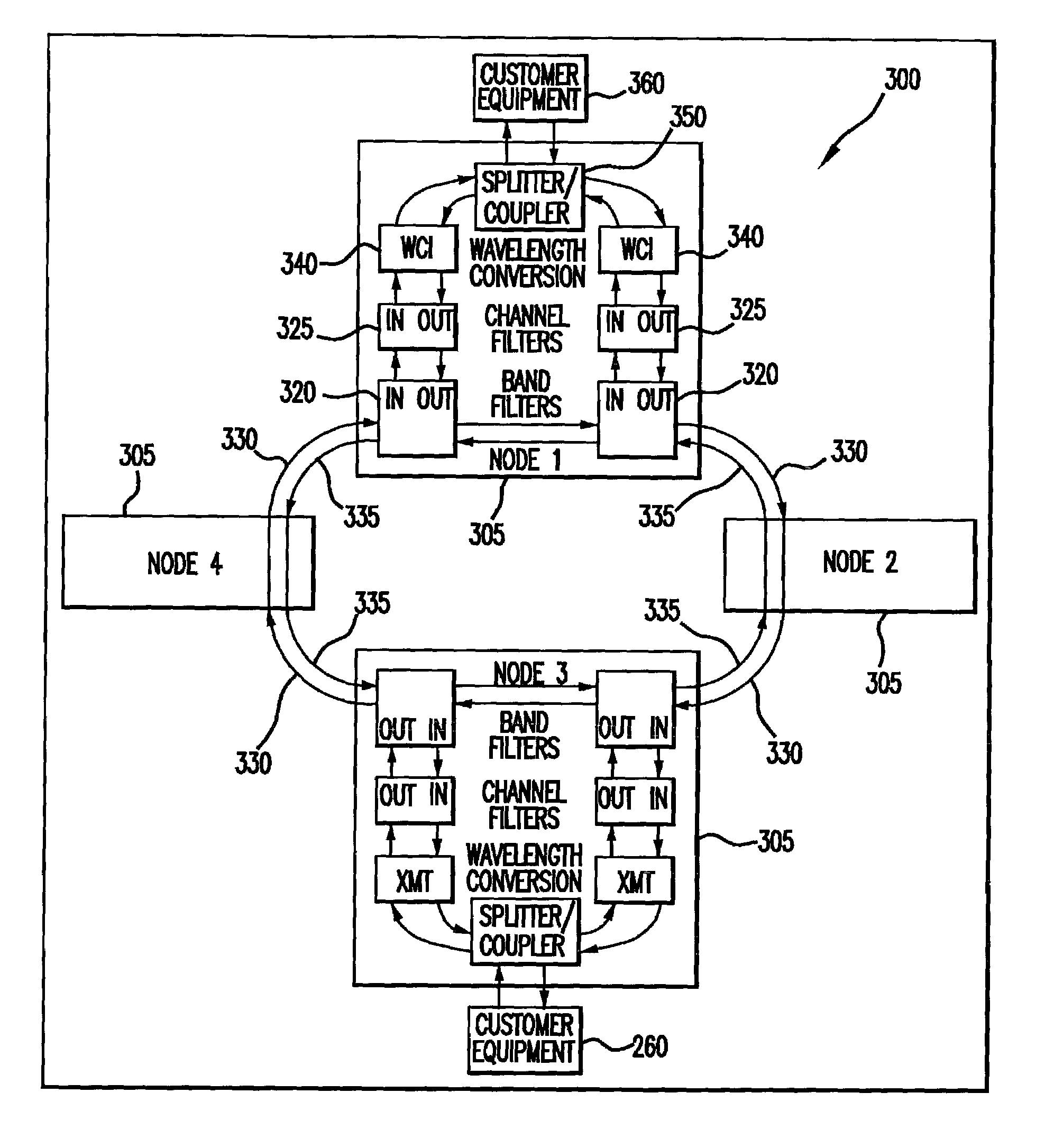
[0017]The present invention generally comprises a method and apparatus for forwarding fault information in an optical network in which at least some of the nodes provide a service (e.g., Gigabit Ethernet, Fiber Channel, or Clear Channel) for which there is no standard alarm signal for propagating fault information that is recognized throughout the entire optical network. However, in some embodiments the network nodes may also provide services, such as SONET and SDH, for which there are well-developed alarm signal protocols.

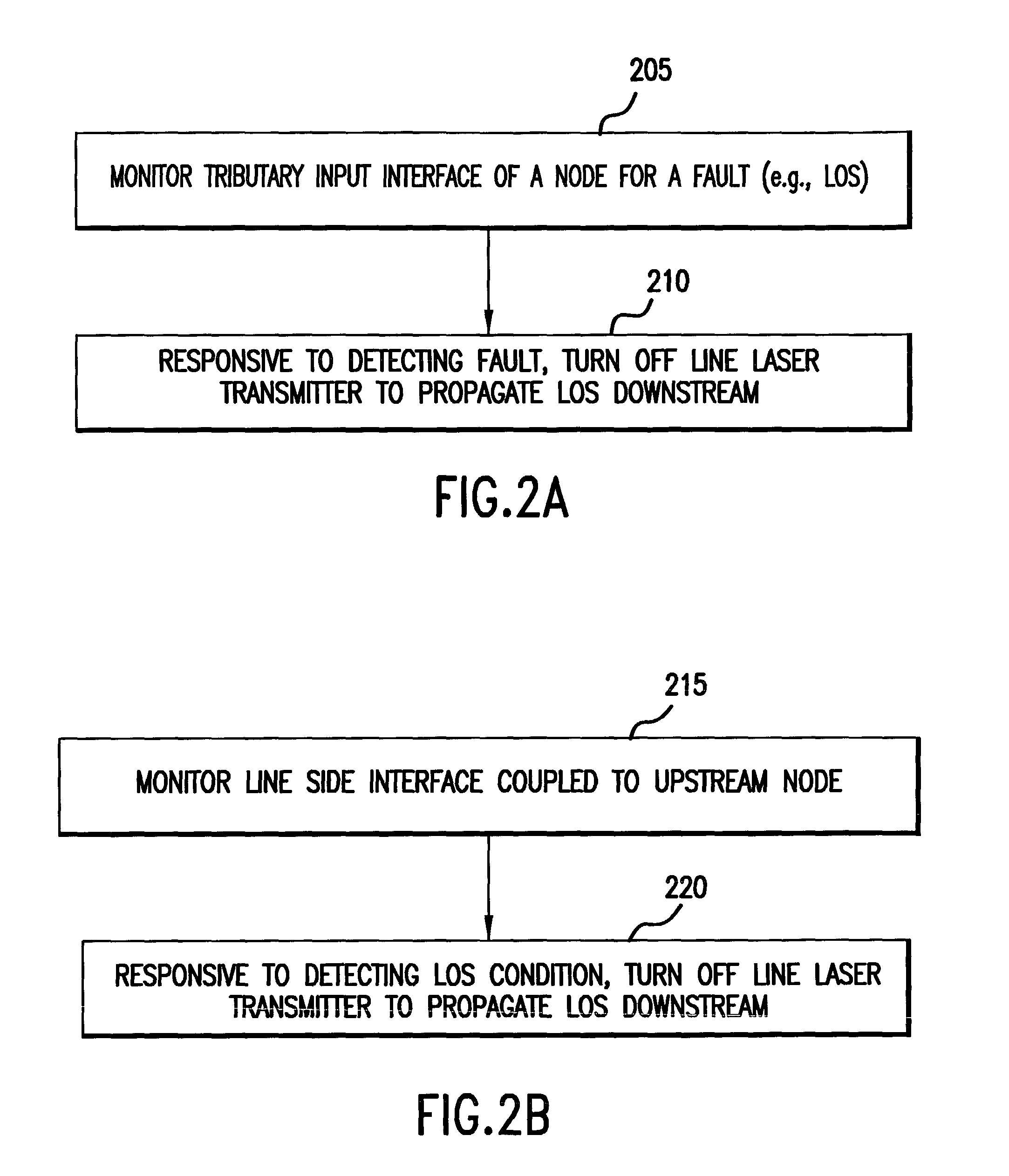
[0018]In the present invention, fault information may be propagated towards a signal destination by turning off a laser transmitter used to propagate the signal towards its destination. For example, in response to a node detecting a fault condition at a tributary interface or a line interface, the node turns off a corresponding laser transmitter used to propagate the signal towards its destination. As a consequence, fault information is rapidly propagated onwards ...


PUM


Abstract

A system and method for forwarding fault information in an optical network is disclosed. Responsive to a fault being detected at a node, the fault information is forwarded to the destination node in the form of a loss-of-signal condition by turning off laser transmitters used to propagate the signal towards its destination. Thus, a node or other network element not capable of generating an alarm signal consistent with an established alarm signaling protocol, such as a SONET alarm indication signal (AIS) or an SDH multiplexer section alarm indication signal MS-AIS, may still forward the fault condition to a downstream element.

Description

RELATED APPLICATIONS[0001]This application claims priority under 35 U.S.C. § 119(e) to United States Patent Application No. 60 / 312,700, entitled “System And Method For Fault Correlation And Forwarding,” filed Aug. 15, 2001, the contents of which are hereby incorporated by reference in their entirety in the present patent application.BACKGROUND OF THE INVENTION[0002]1. Field of the Invention[0003]The present invention relates generally to fault detection and restoration in a unidirectional path switched ring network.[0004]2. Description of Background Art[0005]Unidirectional path switched ring (UPSR) optical networks are of interest for telecommunications. Referring to FIG. 1, in a conventional UPSR network 100, a plurality of optical add drop multiplexer (ADM) nodes are coupled into a ring topology by a plurality of working fibers 110 and protection fibers 115. In a UPSR network traffic added at a source node is simultaneously sent on both the working and protection fibers to a desti...

Claims


Application Information

Patent Timeline
Patent Type & Authority Patents(United States)
IPC IPC(8): H04B10/08
CPCH04B10/07953H04B2210/08
Inventor BHATE, ANURADHAHOULE, DENIS
Owner CIENA
Why Eureka
Try Eureka