Modular construction system

a modular construction and modular technology, applied in the direction of movable shelf cabinets, furniture parts, dismountable cabinets, etc., can solve the problems of not being able to each of the previously-described devices suffers from one or more disadvantages, and the molding apparatus of the wuorio patent cannot be “grown” outside the box created by the four, so as to facilitate the understanding of the invention, the effect of easy repair and replacement of structural members

Inactive Publication Date: 2006-10-03
CULP STEPHEN A
View PDF23 Cites 52 Cited by
  • Summary
  • Abstract
  • Description
  • Claims
  • Application Information

AI Technical Summary

Benefits of technology

[0013]Accordingly, it is an advantage of the invention claimed herein to provide an apparatus for a system of modular construction that may be used to produce an assembled unit from a plurality of subassemblies of structural members and one or more connecting members. It is another advantage of the invention to provide a system that can be used to connect a plurality of subassemblies in a non-planar or “brick and mortar” style construction. It is yet another advantage of the invention to provide a system that allows for the replacement of like structural members with unlike structural members so that repair and replacement of the structural members is easier and less expensive. It is also and advantage of the invention to provide a system that allows for the construction of structurally stable assemblies of limitless dimensions without the use of tools or fastening devices.
[0014]Additional advantages of this invention will become apparent from an examination of the drawings and the ensuing description.
[0015]The invention comprises an assembled unit which includes a first subassembly, a second subassembly, and a connecting member. The first subassembly comprises a plurality of first structural members, each of which includes a plurality of first member sides. At least one of the first member sides includes a first member slot having a first member slot axis. Further, at least one of the first structural members of the first subassembly has at least two first member slots. Each of the first structural members of the first subassembly is detachably connected slot-to-slot to at least one other first structural member to produce the first subassembly. The second subassembly comprises a plurality of second structural members, each of which includes a plurality of second member sides. At least one of the second member sides includes a second member slot having a second member slot axis. Further, at least one of the second structural members of the second subassembly has at least two second member slots. Each of the second structural members of the second subassembly is detachably connected slot-to-slot to at least one other second structural member to produce the second subassembly. Finally, a connecting member having at least two slots is detachably connected slot-to-slot to at least one of the first structural members and to at least one of the second structural members to produce the assembled unit.
[0016]In the preferred embodiment of the invention, the structural members are rectangular in shape, having a pair of equal-lengthed, parallel lengthwise sides, a pair of equal-lengthed, parallel widthwise sides, and a thickness. Also in the preferred embodiment of the invention, the slots on the structural members are located according to a standardized spacing model. More particularly, for a structural member having one or more slots on a lengthwise side, the distance between a widthwise side and the slot axis of the slot that is located nearest the widthwise side is a predetermined slot-to-side distance. For a structural member having one or more slots on a widthwise side, the distance between a lengthwise side and the slot axis of the slot that is located nearest the lengthwise side is a predetermined slot-to-side distance. In addition, for a structural member having two or more slots on any one side, the distance between the slot axes of the slots is a whole-number multiple of the predetermined slot-to-side distance.
[0017]In order to facilitate an understanding of the invention, the preferred embodiments of the invention are illustrated in the drawings, and a detailed description thereof follows. It is not intended, however, that the invention be limited to the particular embodiments described or to use in connection with the apparatus illustrated herein. Various modifications and alternative embodiments such as would ordinarily occur to one skilled in the art to which the invention relates are also contemplated and included within the scope of the invention described and claimed herein.

Problems solved by technology

The previously-described devices, however, each suffer from one or more disadvantages.
None of the previously-described devices can be enlarged by adding additional structural members.
Simply put, the molding apparatus of the Wuorio patent cannot be “grown” outside the box created by the four largest molding elements.
Consequently, neither Wuorio nor Vaeth disclose devices that are scalable.

Method used


Image

  • Modular construction system
  • Modular construction system
  • Modular construction system

Examples


Embodiment Construction

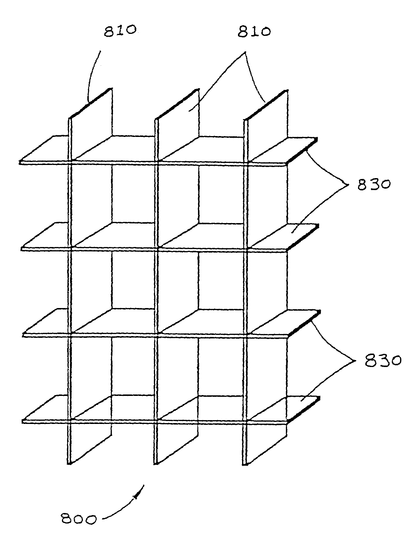
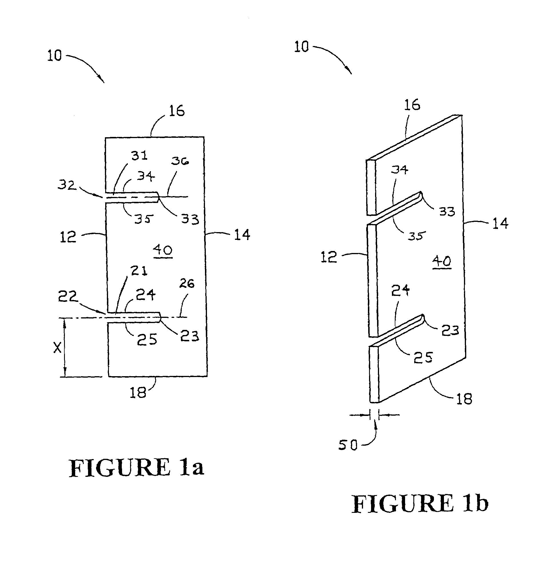
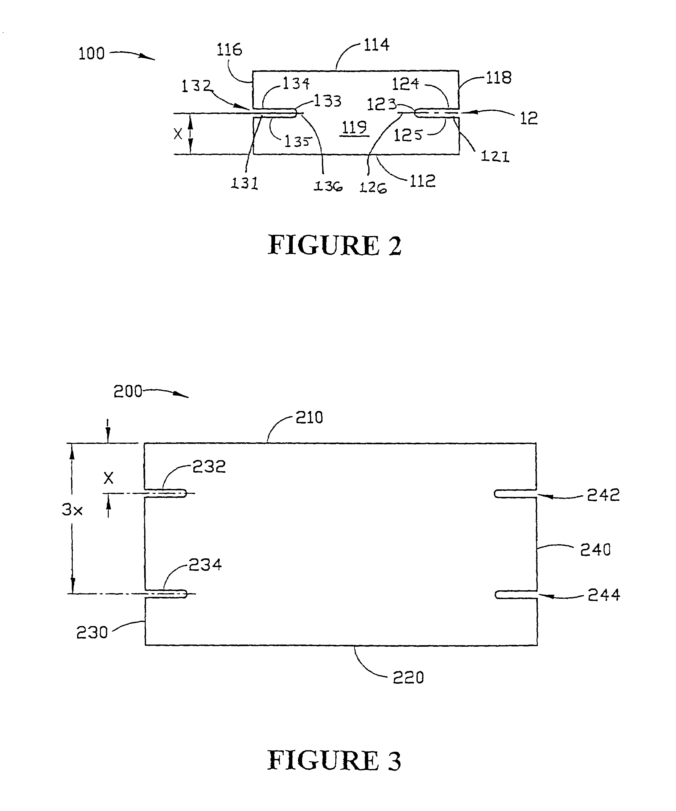
[0037]Referring now to the drawings, FIGS. 1a through 14 illustrate various embodiments of the apparatus of the invention. The basic unit of construction for the system of the invention is a structural member adapted to be detachably connected slot-to-slot to one or more other structural members. Structural member 10 comprises two equal-lengthed, parallel lengthwise sides 12, 14 and two equal-lengthed, parallel widthwise sides 16, 18. Structural member 10 is merely representative of the possible configurations of structural members according to the invention. While the preferred structural member of the system is rectangular in shape, a structural member may be any suitable conventional shape having at least three sides such as a triangle, a square, a trapezoid, another polygon or the like. It is also contemplated that one or more sides of a structural member may be arcuate, curved, bowed, bending, wavy, or angled.

[0038]As shown in FIG. 1a, exemplary structural member 10 also includ...


PUM


Abstract

A system of modular assembly comprising a plurality of structural members. Each of the plurality of structural members comprises at least two slots along a lengthwise side. A first one of the at least two slots defines a first outside slot which is located nearest to a first widthwise side and a second one of the at least two slots defines a second outside slot which is located nearest to a second widthwise side. The distance between the slot axis of the first outside slot and the first widthwise side is a predetermined slot-to-side distance, and the distance between the slot axis of the second outside slot and the second widthwise side is a whole-number multiple of the predetermined slot-to-side distance. The distance between each of the slot axes of the at least two slots along one of said lengthwise sides is a whole-number multiple of the predetermined slot-to-side distance. The plurality of structural members comprises a first vertical structural member, a second vertical structural member, a first horizontal member and a second horizontal structural member. The first outside slot of the first vertical structural member is detachably connected slot-to-slot to the first outside slot of the first horizontal structural member, the second outside slot of the first vertical structural member is detachably connected slot-to-slot to the first outside slot of the second horizontal structural member, the first outside slot of the second vertical structural member is detachably connected slot-to-slot to the second outside slot of the first horizontal structural member, and the second outside slot of the second vertical structural member is detachably connected slot-to-slot to the second outside slot of the second horizontal member such that the first vertical structural member is substantially parallel to the second vertical structural member and substantially perpendicular to the first horizontal structural member and the second horizontal structural member.

Description

CROSS-REFERENCE TO RELATED APPLICATIONS[0001]This application is a continuation of the continuation application entitled Modular Construction System, which was filed on Aug. 6, 2003, assigned Ser. No. 10 / 634,685 and issued as U.S. Pat. No. 6,845,871. The continuation application was filed as a application of the continuation-in-part application entitled System for Modular Construction, which was filed on Jul. 11, 2002, assigned Ser. No. 10 / 192,940 and issued as U.S. Pat. No. 6,615,999. The continuation-in-part application was filed as a application continuation in part of the application entitled System for Modular Construction, which was filed on May 7, 1999, assigned a Ser. No. 09 / 307,229, and subsequently abandoned. The disclosures of the co-pending continuation application, the issued continuation-in-part application and the abandoned application are fully incorporated herein by reference.FIELD OF INVENTION[0002]This invention relates generally to an apparatus for producing a sc...

Claims


Application Information

Patent Timeline
Patent Type & Authority Patents(United States)
IPC IPC(8): A47B43/00
CPCA47B47/042A47B2230/0085
Inventor CULP, STEPHEN A.
Owner CULP STEPHEN A
Why Eureka
Try Eureka