Air/fuel injection system having cold plasma generating means

a technology of air/fuel injection system and cold plasma, which is applied in the field of systems, can solve the problems of increasing the air flow rate, increasing the volume of the combustion region, and increasing the cost of the double-stage chamber, so as to improve the operation of the existing combustion chamber, reduce the volume of the combustion region, and increase the combustion efficiency

Active Publication Date: 2006-10-03
SN DETUDE & DE CONSTR DE MOTEURS DAVIATION S N E C M A
View PDF15 Cites 42 Cited by
  • Summary
  • Abstract
  • Description
  • Claims
  • Application Information

AI Technical Summary

Benefits of technology

[0010]The main object of the present invention is therefore to alleviate such drawbacks by providing a system for injecting an air / fuel mixture into a combustion chamber which makes it possible to increase the resistance of the combustion region to flameout, while still maintaining a simple architecture and limiting polluting emissions.

Problems solved by technology

However, increasing the air flow rate is not sufficient to completely eliminate the zones of stoichiometric mixing within the combustion region.
In general, making the combustion leaner results in an increase in the vulnerability of the combustion region to extinction, so that the idling phases of the engine can no longer be obtained.
Also this solution appears satisfactory, a double-staged chamber is still difficult to control and is expensive owing to the doubling of the number of fuel injectors as compared with a conventional single-head combustion chamber.
The main drawback of such multipoint injection systems lies in the complexity of the various fuel circuits and of the regulating system.
However, such an injection system is not completely satisfactory.
Firstly, the multipoint architecture remains complex and difficult to control.
Secondly, the high-energy discharge takes place only in the main fuel flow, which limits the effectiveness of such an injection system in combating the risk of extinction of the combustion region.

Method used


Image

  • Air/fuel injection system having cold plasma generating means
  • Air/fuel injection system having cold plasma generating means
  • Air/fuel injection system having cold plasma generating means

Examples


Embodiment Construction

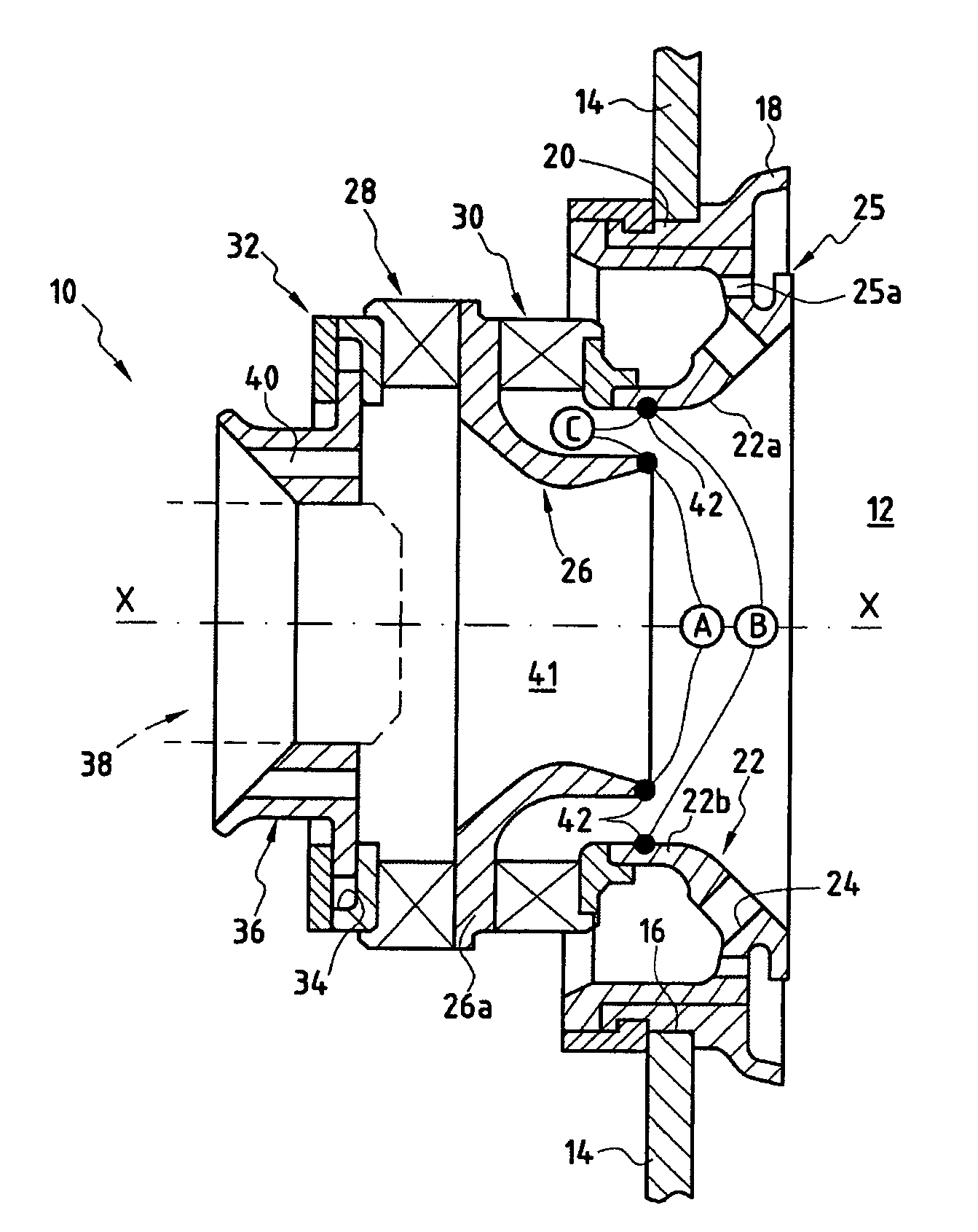
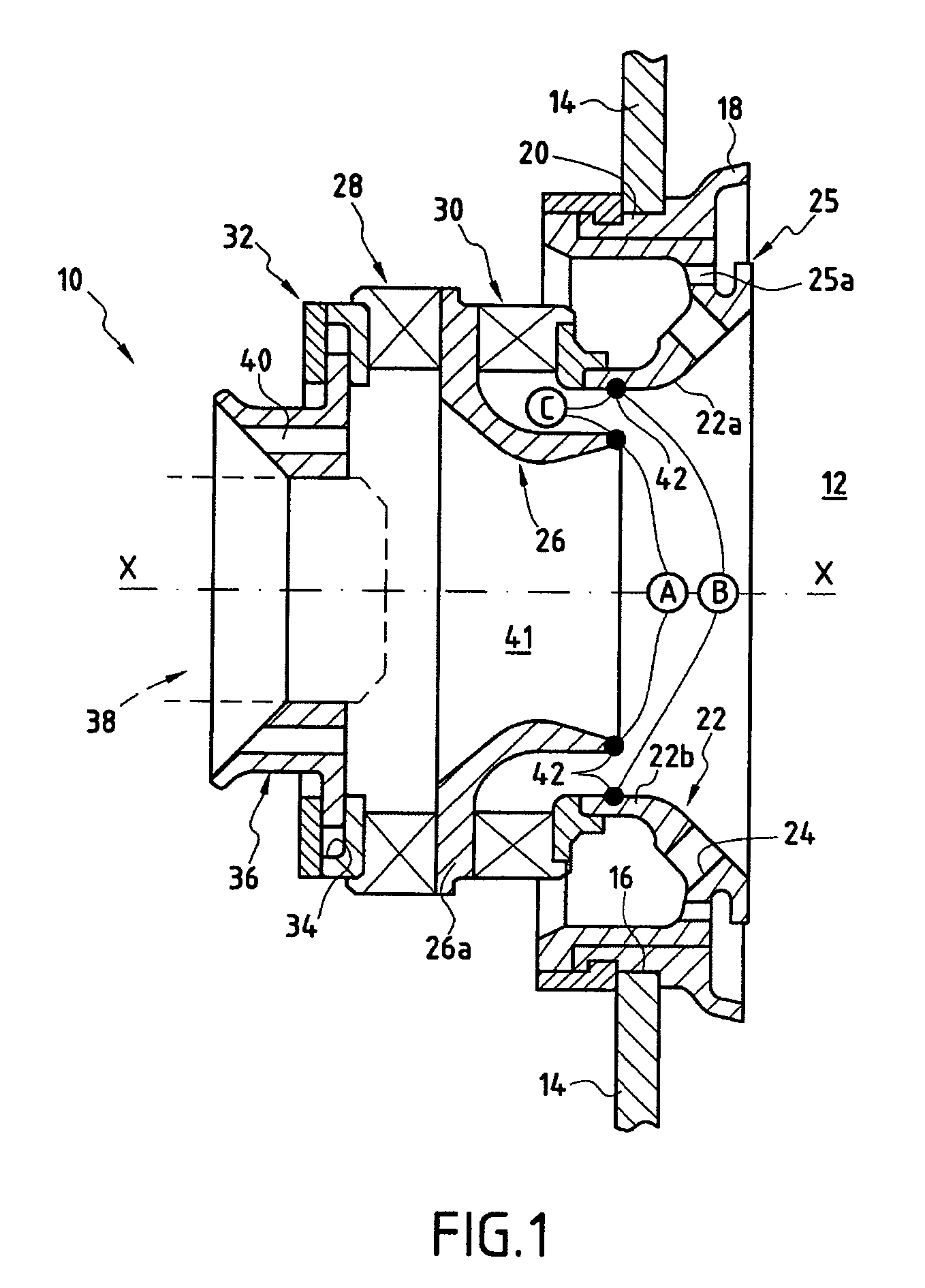
[0027]FIG. 1 shows, in a longitudinal section, an injection system according to one embodiment of the invention. In this embodiment, the injection system is of the aeromechanical type.

[0028]The injection system 10 of longitudinal axis X—X is essentially composed of a tubular structure for the flow of an air / fuel mixture towards the combustion region of a combustion chamber 12 of a turbomachine. This air / fuel mixture is intended to be burnt in the combustion chamber 12.

[0029]The combustion chamber 12 is, for example, of the annular type. It is bounded by two annular walls (not shown in FIG. 1) which are spaced apart radially with respect to the axis of the turbomachine and are connected upstream by a chamber back wall 14. The chamber back wall 14 has a plurality of ports 16 uniformly spaced apart along a circle around the axis of the turbomachine. Fitted into each of these ports 16 is an injection system 10 according to the invention. The gases emanating from the combustion of the ai...


PUM


Abstract

A system for injecting an air / fuel mixture into a turbomachine combustion chamber, including a hollow tubular structure for the flow of the air / fuel mixture into the combustion chamber; a fuel injection device placed at an upstream end of the hollow tubular structure, and an air injection device placed downstream of the fuel injection device. The system also includes a cold plasma generator placed downstream of the air injection device so as to generate active species in the flow of the air / fuel mixture and to cause prefragmentation of the molecules of the air / fuel mixture. The system further includes a device for controlling the cold plasma generator depending on the speed of operation of the turbomachine.

Description

BACKGROUND OF THE INVENTION[0001]The present invention relates to the general field of systems for injecting an air / fuel mixture into a turbomachine combustion chamber. It relates more particularly to an injection system provided with a cold plasma generator capable of controlling the reactivity of the air / fuel mixture during its injection into the combustion chamber.[0002]The main objective of the conventional process of designing and optimizing a turbomachine combustion chamber is to reconcile the operational performance characteristics of the chamber (combustion efficiency, stability range, ignition and relight range, lifetime of the combustion region, etc.) according to the envisaged mission of the aircraft on which the turbomachine has been mounted, while minimizing the polluting emissions (nitrogen oxides, carbon monoxide, unburnt hydrocarbons, etc.). To do this, it is possible to vary in particular the nature and the performance characteristics of the system for injecting the...

Claims


Application Information

Patent Timeline
Patent Type & Authority Patents(United States)
IPC IPC(8): F02C1/00F02G3/00H05H1/24F23R3/00F23R3/04F23R3/14F23R3/28
CPCF23R3/286F23C2900/99005F23K2301/101F23K2300/101
Inventor CAZALENS, MICHELBEULE, FREDERIC
Owner SN DETUDE & DE CONSTR DE MOTEURS DAVIATION S N E C M A
Why Eureka
Try Eureka