
RFID encoder and verifier

a technology of encoder and verifier, applied in the field of labeling systems, can solve the problems of limiting the range of optical readers, placing rfid labels, and many businesses or users not having suitable rfid readers to read rfid tags

Active Publication Date: 2006-10-03
TSC AUTO TECH
View PDF39 Cites 54 Cited by
  • Summary
  • Abstract
  • Description
  • Claims
  • Application Information

AI Technical Summary

Benefits of technology

"The invention is a RFID device that can program RFID tags using information from a data stream, such as a barcode, and apply the tag to a package that contains a barcode or other optically readable label. This allows for the placement of both types of labels on packages using existing systems. The RFID device can also verify the proper programming of the RFID tag and detect any defects in the label. The invention also includes interpreters, emulations, or look-up or substitution tables that allow the RFID applicator device to convert the information needed for programming an RFID tag or label. Additionally, the invention allows for easy migration into competitor applications by supporting various languages."

Problems solved by technology

One disadvantage of optically readable labels is that the optical reader and the label must be within a specific spatial relationship to each other, such as within a line of sight or along a perpendicular scan direction, or is limited in range by the optical reader.
This may be beneficial because RFID label technology is not as widespread as barcode technology, and many businesses or users may not have suitable RFID readers to read the RFID tag.
However, because RFID label technology is not as widespread, many users may only have barcode applicators for placing the barcode label on the package, thereby preventing placement of RFID labels.
However, such printers and applicators can be costly.
For example, the barcode may be unreadable or represent incorrect information.

Method used


Image

  • RFID encoder and verifier
  • RFID encoder and verifier
  • RFID encoder and verifier

Examples


Embodiment Construction

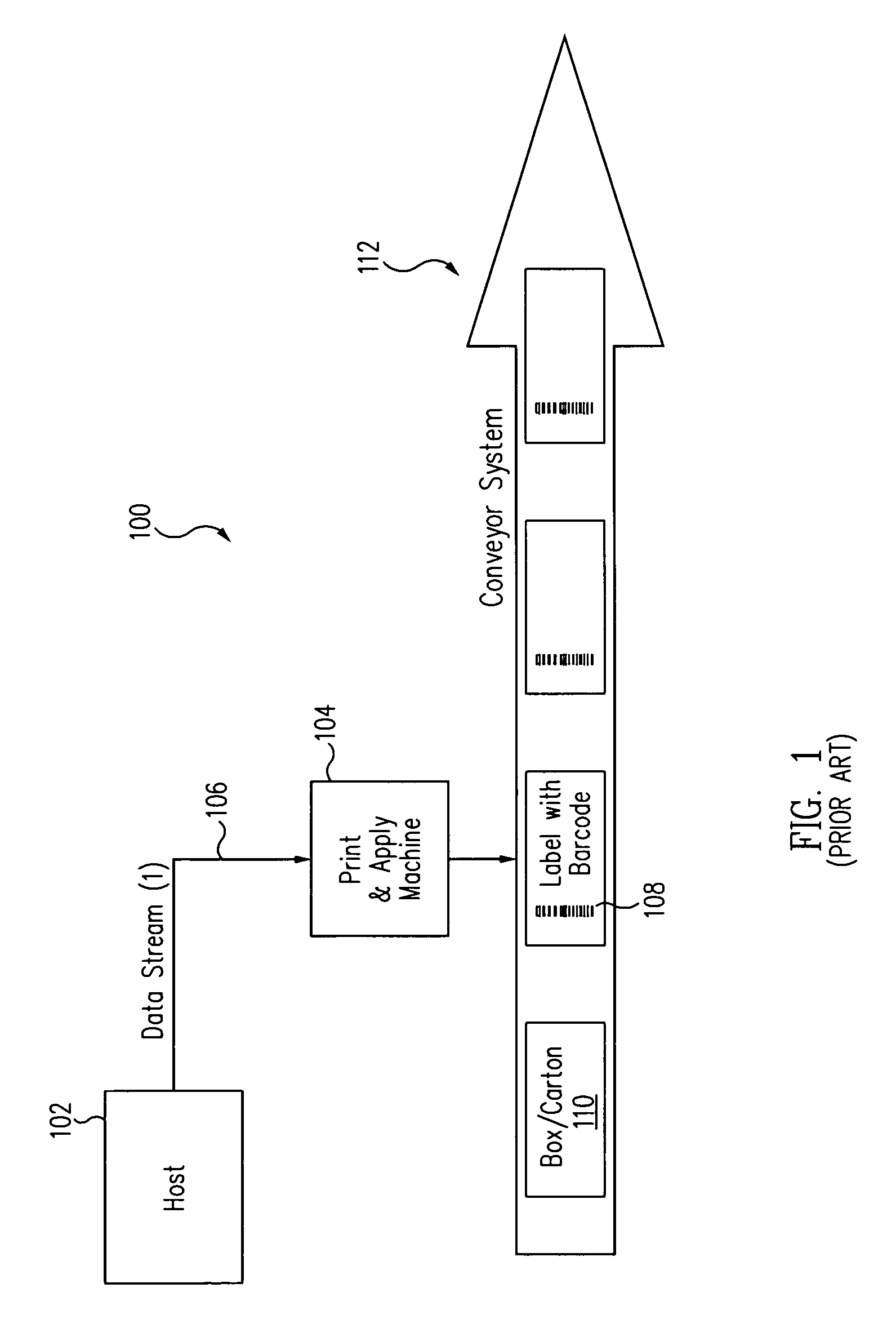
[0025]FIG. 1 shows a block diagram of a conventional print and apply system 100 for applying optically readable or barcode labels. System 100 includes a host computer 102, which can be a conventional personal computer coupled to a local area network (LAN). A print and apply device 104 receives information via a data stream 106 from host computer 102 that includes a host application, typically specific to the system through an electrical and software interface. The electrical interface can be any suitable communication means, such as, but not limited to, a serial or parallel physical link, an Ethernet connection, or a wireless link. The data stream contains various commands, such as line, box, font, and barcode commands, for printing lines, boxes, text, barcodes, and other images. The data stream is transmitted to the printer portion of device 104 in specific languages to cause the printer to print an image on a label or other media.

[0026]Typically, each manufacturer uses a unique an...


PUM


Abstract

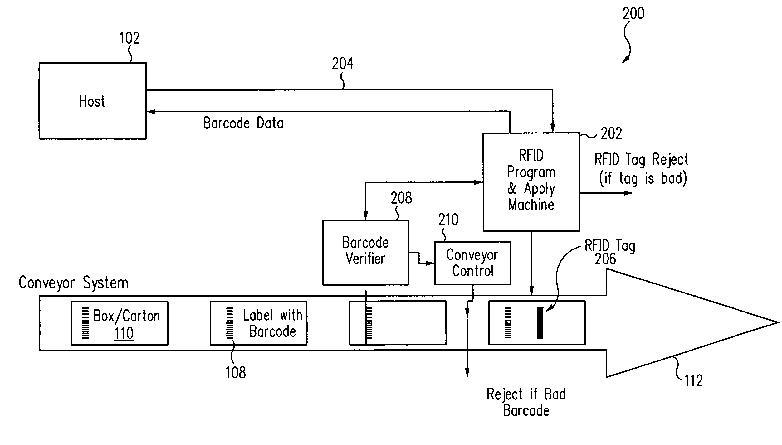
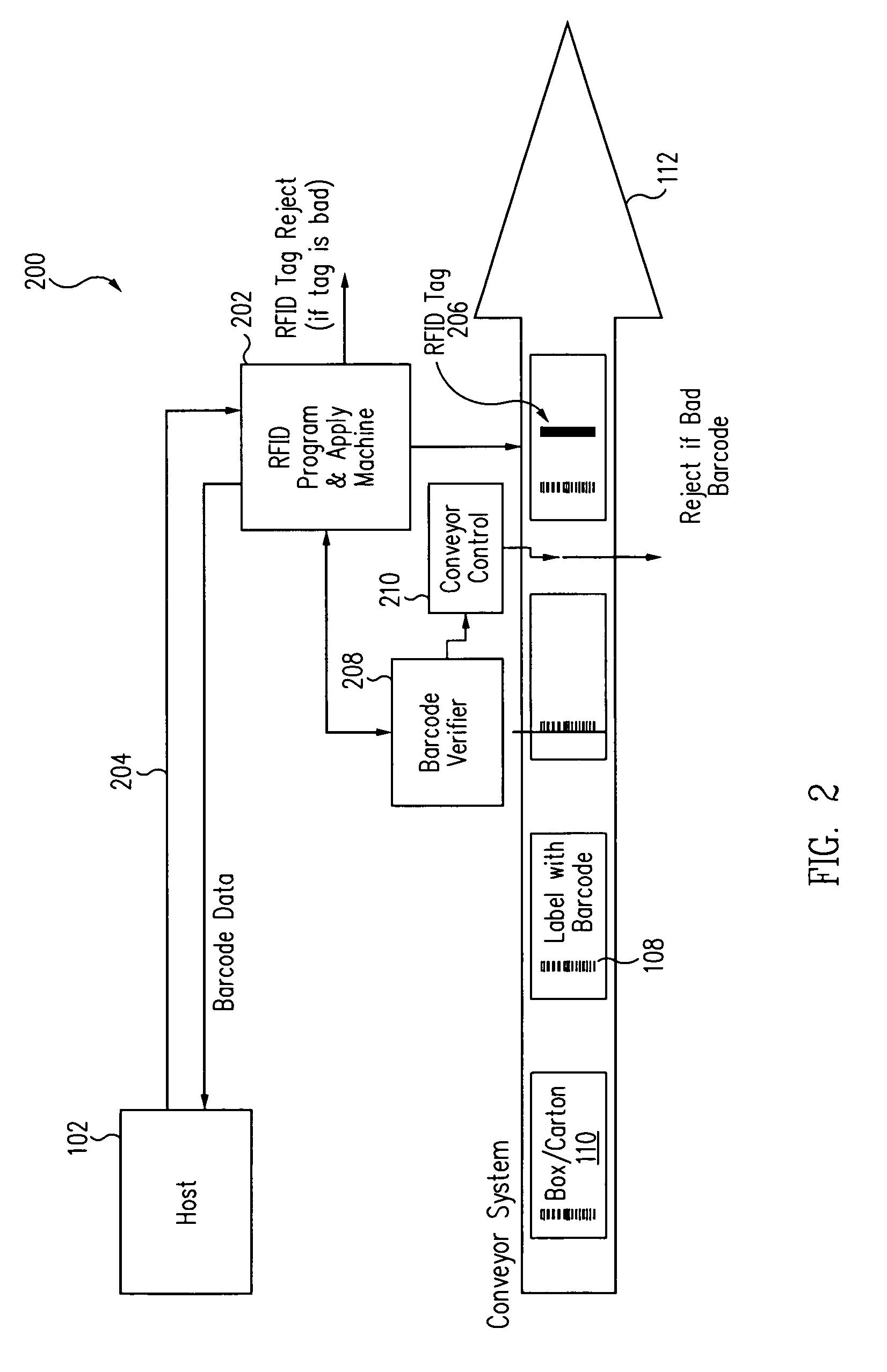
An RFID encoder is used in conjunction with a barcode print and apply system. The RFID encoder utilizes information obtained from a data stream from a host computer, from a corresponding barcode label, or other source to program an RFID label. The programmed label can then be applied with an integrated applicator or an external applicator. The RFID encoder can also verify that an RFID tag or label has been properly encoded and has the same content as the corresponding barcode label. The RFID can further verify that the barcode has been properly printed. If both barcode and RFID tag contain the correct data, both types of labels are attached to a package, enabling the package to be read optically and with radio frequency signals.

Description

BACKGROUND[0001]1. Field of the Invention[0002]The present invention relates to labeling systems, and in particular, to programming and / or verifying RFID labels prior to application onto products already having optically readable information such as barcodes.[0003]2. Related Art[0004]Typically, products stored in cartons or boxes are identified by a label on the outside of the carton or box. Identifying information may also be printed directly onto the carton with inkjet or any other suitable printing technology. The label may have optically readable information, such as a UPC barcode. These labels allow optical readers using a laser beam to scan the information contained thereon, such as description, price, date packaged, or any other usable data. One disadvantage of optically readable labels is that the optical reader and the label must be within a specific spatial relationship to each other, such as within a line of sight or along a perpendicular scan direction, or is limited in ...

Claims


Application Information

Patent Timeline
Patent Type & Authority Patents(United States)
IPC IPC(8): G06K7/10G06K15/00H04Q5/22G06K1/12G06K7/00
CPCG06K1/12G06K7/00G06K17/0025
Inventor CHAPMAN, THEODORE A.LE, VAN L.BALLESTY, CAROL D.EDWARDS, ANDREW W.
Owner TSC AUTO TECH
Learn More