Electrical energy storage cell and electrical energy storage module including the same

a technology of electrical energy storage and energy storage cells, applied in the direction of cell components, sustainable manufacturing/processing, wound/folded electrode electrodes, etc., can solve the problems of reducing the efficiency of charging and discharging, sharp reduction in performance, and power loss generation, so as to improve the heat dissipation characteristic of cells, reduce current collector resistance, and efficiently dissipate internally generated heat

Inactive Publication Date: 2009-05-28
MITSUBISHI ELECTRIC CORP
View PDF1 Cites 43 Cited by
  • Summary
  • Abstract
  • Description
  • Claims
  • Application Information

AI Technical Summary

Benefits of technology

[0016]Since each of the cathode current collector foil and the anode current collector foil is electrically coupled together in a lamination direction at the non-cutaway (non-recessed) portions, an electrical energy storage cell according to the present invention can dissipate efficiently internally generated heat from the current collector foil via electrode terminal, as well as lowering a current collector resistance. Furthermore, since an electrolyte reservoir that makes a contact with the exposed separator is provided at each of the cutaway portions, as well as facilitating the electrolyte to migrate to the separator, the storage cell can compensate for excess or deficiency of an electrolyte in the separator using the electrolyte reservoir, to maintain the separator filled with the electrolyte at all times.
[0017]Furthermore, the electrical energy storage module according to the present invention can improve a heat dissipation characteristic of the cells, as well as reducing interconnection resistance between the cells. These and other features, advantages and objects of the present invention will be further understood and appreciated by those skilled in the art by reference to the following drawings.

Problems solved by technology

When used for brake regeneration in servo motors, elevator traction machines, or electric railroad cars, and for regeneration of electric motors of hybrid vehicles or the like, such capacitors are requested to achieve the performance of repetitive charging and discharging for a large current capacity that is more than 100 A. When the large current flows, power loss is generated in proportion to internal resistance and the square of the current, thereby reducing efficiency in the charging and discharging.
Moreover, because of the power loss automatically resulting in heat generation, unless the current collector foil, which is a thermal conductor, rapidly carries out heat dissipation, then the temperature inside the electrical energy storage cell increases, which leads to sharp reduction in performance, thus causing reduction in life span.
In particular, during charging, since the electrode swells and allows electrolyte to be taken in, it is likely to cause a deficiency of the electrolyte, which has been a factor that accelerates degradation.
Because in the construction in which metallic tubs are ultrasonically bonded at a several places of the current collector foil and are connected to current terminals for drawing out of the casing, only limited areas of the metallic tubs are bonded to the current collector foil, a problem has been that the heat generated from the current collector foil cannot efficiently be dissipated, as well as a problem of the current collector resistance that cannot be reduced.
Another problem has been that the heat generated from the current collector foil cannot efficiently be dissipated because the thermal conductivity of the separator is lower than that of the current collector foil in the construction in which the separator stretches out to the outside in the axial direction.
Furthermore, in the configuration in which edge portions are provided where no electrode layers oppositely projecting from the separator along the roll core axis are applied and in which the edge portions are connected to the edge portion, still another problem has been that although heat dissipation and interconnection resistance are reduced, the electrolyte becomes difficult to migrate, resulting in a deficiency of the electrolyte in some part of the internal separator, which hastens degradation of the separator.

Method used


Image

  • Electrical energy storage cell and electrical energy storage module including the same
  • Electrical energy storage cell and electrical energy storage module including the same
  • Electrical energy storage cell and electrical energy storage module including the same

Examples


embodiment 1

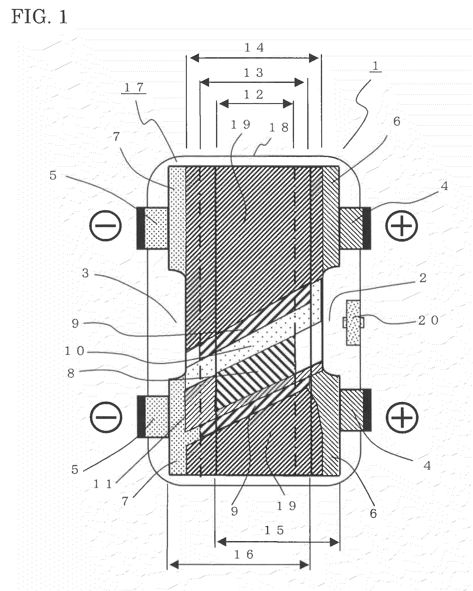
[0029]FIG. 1 is a partially cutaway schematic plan view of an electrical energy storage cell according to Embodiment 1 for implementing the present invention. The electrical energy storage cell according to Embodiment 1 will be described in the case of an electric double-layer capacitor. The invention is not limited to this one, but can apply in the same way to a lithium-ion battery cell, a lithium-ion capacitor, or the like.

[0030]An electrical energy storage cell 1 in the present embodiment comprises two cathode (positive electrode) terminals 4 and two anode (negative electrode) terminals 5, whereby heat build-up in the cell is reduced and current collection thereof is enhanced. A cathode (positive electrode) current collector foil cutaway portion (also called cathode foil cutaway portion, or cutaway portion, or recessed portion), designated at 2, and an anode (negative electrode) current collector foil cutaway portion (also called anode foil cutaway portion, or cutaway portion, or...

embodiment 2

[0066]Next, an electrical energy storage module using the electrical energy storage cell according to the present invention will be described referring to FIGS. 8 and 9. FIG. 8A and FIG. 8B show a schematic internal plan view and a cross-sectional view, respectively, illustrating a three-cell storage module using the electrical energy storage cell of a flat roll configuration, according to Embodiment 2. The electrical energy storage cell referred to in the present embodiment is one that has been described in Embodiment 1. Three electrical energy storage cells 1 are arranged inside a casing for containing the module (hereinafter called a module casing), designated by reference numeral 40, of aluminum formed by a drawing process. In one of the electrical energy storage cells 1 and its adjacent cell, two of the cathode terminals 4 of the former and two of the anode terminals 5 of the latter are connected together using heat dissipation plates 41 made of a copper plate. In the same stor...

embodiment 3

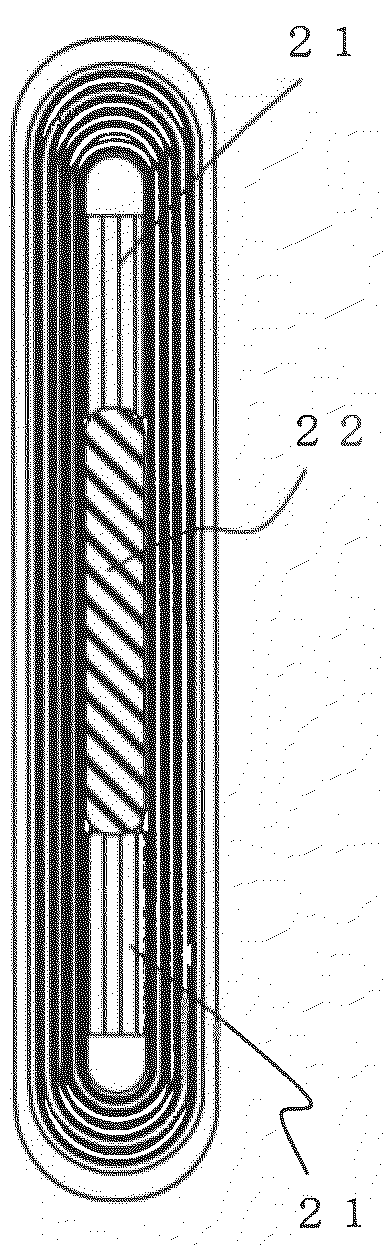
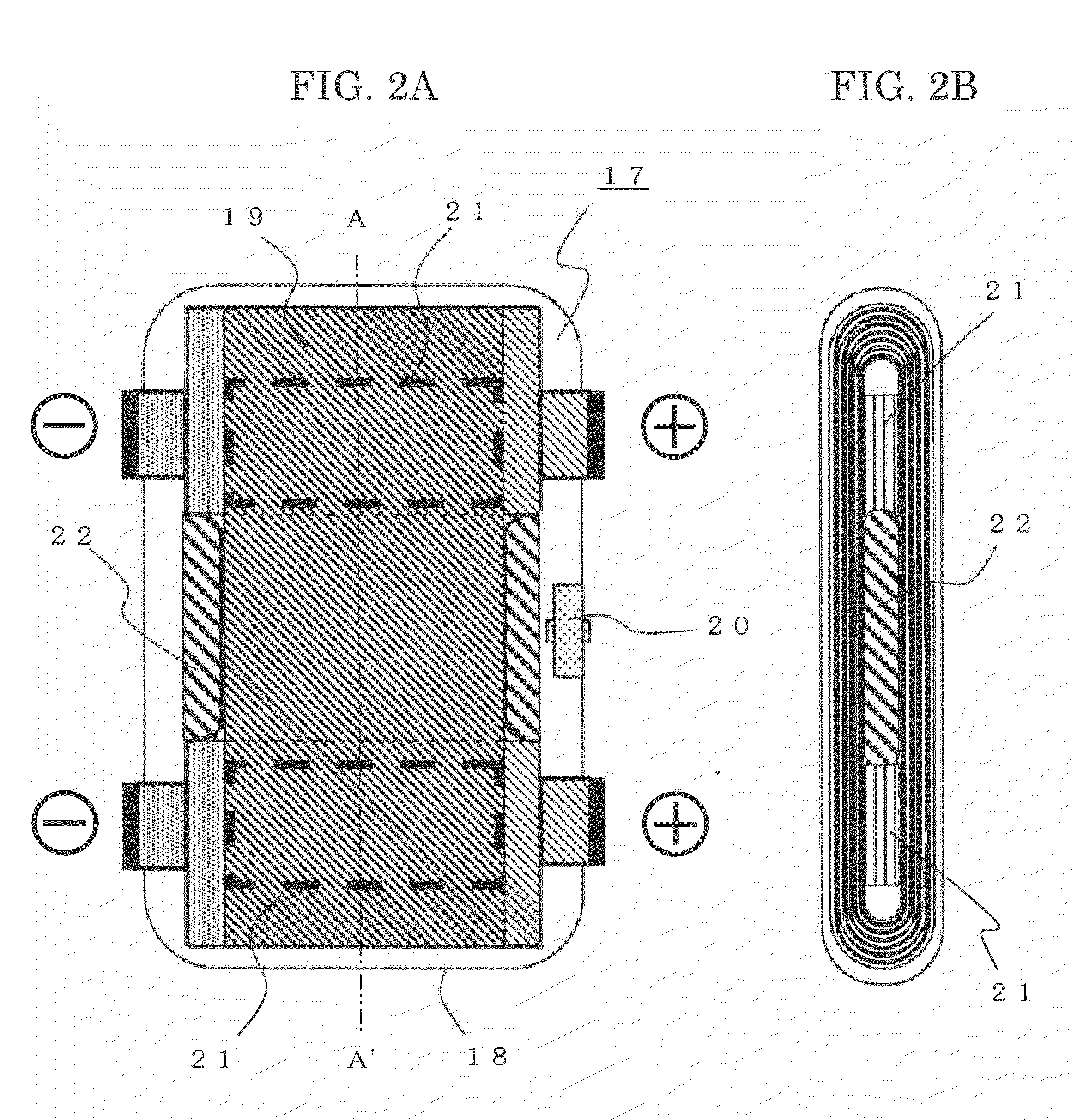
[0071]FIG. 10 is a plan view illustrating the flat roll electrical energy storage cell according to Embodiment 3 of the present invention. A difference between the present embodiment and Embodiment 1 is that the electrolyte reservoir 22 of the current collector foil cutaway portion is not made to pass through the core portion, with the configuration remaining the same except for this difference. In the present embodiment, although the electrolyte reservoir 22 of the current collector foil cutaway portion is not inserted into the core portion, the separator, which is exposed from the current collector foil at the cathode foil cutaway portion 2 and anode foil cutaway portion 3, make a contact with the electrolyte reservoir 22 of the current collector foil cutaway portion, thus enabling sufficient transfer of the electrolyte.

[0072]Further, because the core electrolyte reservoir 21 is disposed, and the electrolyte released from the separator to the electrolyte reservoir 22 is absorbed b...


PUM

PropertyMeasurementUnit
voltageaaaaaaaaaa
voltageaaaaaaaaaa
voltageaaaaaaaaaa

Abstract

The storage cell comprises a flat roll electrode that includes a strip of positive electrode having a positive electrode current collector foil and a positive electrode layer formed thereon, a strip of negative electrode having an electrode current collector foil and a negative electrode layer formed, and a strip of electrically insulated separator, the strip of positive electrode and the strip of negative electrode being wound into a flat roll configuration with the strip of electrically insulated separator sandwiched therebetween; a sealed casing that hermetically seals the flat roll electrode impregnated with an electrolyte; a positive terminal and a negative terminal each electrically insulated from the sealed casing, connected to the positive current collector foil and the negative current collector foil, respectively.

Description

FIELD OF THE INVENTION[0001]The present invention relates to electrical energy storage cells wound into a flat roll configuration, such as electric double-layer capacitors, lithium-ion battery cells, or lithium-ion capacitors, and more particularly to electrical energy storage modules configured by interconnecting in series a plurality of such cells.BACKGROUND OF THE INVENTION[0002]Electrical energy storage cells of a flat roll configuration, contained in a casing include electric double-layer capacitors, lithium-ion battery cells, lithium-ion capacitors, and the like.[0003]The electric double-layer capacitor is one such that polarization electrodes—cathode, i.e., positive electrode and anode, i.e., negative electrode—are placed that face to each other by way of a separator, and double-layer capacitance to be formed on surfaces of the polarization electrodes in an electrolytic solution is used.[0004]The lithium-ion battery cell uses oxide compound such as of cobalt, nickel, manganes...

Claims


Application Information

Patent Timeline
Patent Type & Authority Applications(United States)
IPC IPC(8): H01M6/10H01G2/04H01G2/08H01G11/06H01G11/18H01G11/22H01G11/52H01G11/66H01M4/13H01M4/70H01M10/0566H01M10/0587H01M10/60H01M10/613H01M10/647H01M10/653H01M10/6553H01M10/6554H01M50/538
CPCH01G9/016H01G9/10H01G9/155H01G11/18H01G11/52H01G11/58Y02E60/122H01G11/80H01M2/263H01M10/0431H01M10/0525H01M10/0587Y02E60/13H01G11/70Y02E60/10H01M50/538Y02P70/50H01G11/28H01G11/12H01G11/74
Inventor MITSUDA, KENROTAKEMURA, DAIGOHIROI, OSAMUAIHARA, SHIGERU
Owner MITSUBISHI ELECTRIC CORP
Why Eureka
Try Eureka