Queue-based bag forming system and method

a technology of forming system and padded bag, which is applied in the field of system and method of forming padded bags, can solve the problems of special difficulties in the manufacturing process, loss of the manufacturer, irritation and delay on the part of the customer, etc., and achieves the effects of facilitating capture and heat transfer, preventing short circuit development, and increasing clamping pressur

Inactive Publication Date: 2006-10-03
AUTOMATED SOLUTIONS
View PDF50 Cites 26 Cited by
  • Summary
  • Abstract
  • Description
  • Claims
  • Application Information

AI Technical Summary

Benefits of technology

[0019]The method of the present invention may further include, as part of the step of forming transverse seal-cuts, the step of interposing the envelope between a sealer bar and a compliant anvil, the sealer bar having an initial temperature below the softening point of the plastic and comprising a sealing surface and an optional ridge projecting therefrom for increasing clamping pressure along a cut line. The sealing surface itself is smaller, widthwise, than the sealer bar, so that on either side of the sealing surface there are regions where pressure may be applied without applying heat. A selected clamping pressure, sufficient to compress the padding element to a near-solid state in order to facilitate capture and heat transfer, is applied in order to clamp the layers of the film envelope between the sealer bar and the anvil. Rather than applying the clamping pressure to the sealer bar, the clamping pressure may be applied to the anvil. The sealing surface is then heated to a selected sealing temperature, such that the layer of padding element is captured in the layers of thermoplastic film in the region of the sealing surface and, because of the effect of additional pressure in the area of the ridge if it is present, the envelope is at least partially severed in the region of the ridge to define the end of a first bag and the leading edge of the next bag. In the regions of the sealer bar outside the sealing surface, the padding element is held in place so that it cannot shrink away from the seal. The sealing surface and plastic are then cooled (or allowed to cool) to a temperature below the softening point of the plastic and the clamping pressure is removed. Alternatively to the use of a severing ridge, a seal band with no ridge and a cutting apparatus such as a knife could be used to separate one bag from another.
[0020]In a further feature of the present invention, a nonstick layer may be interposed between the sealer bar and the envelope. If a perforated cut is preferred, a plurality of heat conducting members may be interposed between the sealer bar and the envelope to form retention regions connecting the two bags, such that the seal-cut is a perforation. These heat conducting members may be spring wires, spring bands, or any other material suitable for drawing, in a localized fashion, sufficient heat away from the ridge such that the heat remaining in the area is insufficient to sever the bag. The dimensions of these areas will necessarily depend upon the characteristics of the materials being sealed and will preferably be chosen to allow the bags to be disconnected from each other fairly easily. These conducting members should be electrically isolated from the sealer bar so as to prevent a short circuit from developing.

Problems solved by technology

Because of a wide variety of styles, constructions, fabrics, and the like within a single manufacturer's catalog, because such items are comparatively expensive, and because of traditional production practices, it is common for a furniture manufacturing facility to produce pieces of furniture of differing lengths on a piece-by-piece basis, rather than manufacturing a run of a single style all at the same time.
However, it has also been recognized that the type of damage against which the padding element protects is generally only realized at the ends of each piece, such as on the arms of a sofa.
This allows the bag manufacturer to realize a materials costs savings while providing for easier warehousing processes, but doing so introduces special difficulties into the manufacturing process.
The risk associated with using a bag that fits the item improperly is that the item will incur damage during shipment, which results in a loss to the manufacturer and irritation and delay on the part of the customer.
However, given a wide variety of sizes and the unpredictable nature of the business of custom furniture manufacturing, it is often economically infeasible to carry a supply of pre-made bags of every size needed, particularly if the bags vary both in their length and in the arrangement of the padding element.
This practice is wasteful of bagging materials when these bags are used on smaller items.
A further problem associated with the formation of bags is in the length of the production line needed to form a single windowed bag.
However, in a typical bag forming apparatus, the distance along the production line required for forming the sandwich, folding the sandwich, and sealing the end is longer than a typical bag, and may in some cases be longer than the total length of two, three, or more bags.
This does not present a problem when bags of the same size are formed all at the same time, but if only a single bag of accustom size and arrangement is needed, then a substantial amount of waste is generated as the rolls must be advanced far enough to allow that custom bag to reach the end of the production line.
A further problem associated with the formation of windowed bags is the tendency of the padding element to shrink away from the heat sealing mechanism and to become disconnected within the film-pad sandwich.
However, because the padding element is largely free to “float” within the sandwich, if a hot wire is applied to the seal-cut location, the unmelted portion of the padding element tends not to remain integral with the melted portion of the padding element, and this separation allows the unmelted portion to float freely.
This is undesirable because the padding element needs to remain at the ends of the bag.
This problem could be solved by attaching the padding element along its face to the film layers, but this would reduce the effectiveness of the padding element to prevent damage to the bulky article, and in certain applications (such as shrink-wrapping applications) may cause the padding element to become rumpled.

Method used


Image

  • Queue-based bag forming system and method
  • Queue-based bag forming system and method
  • Queue-based bag forming system and method

Examples


Embodiment Construction

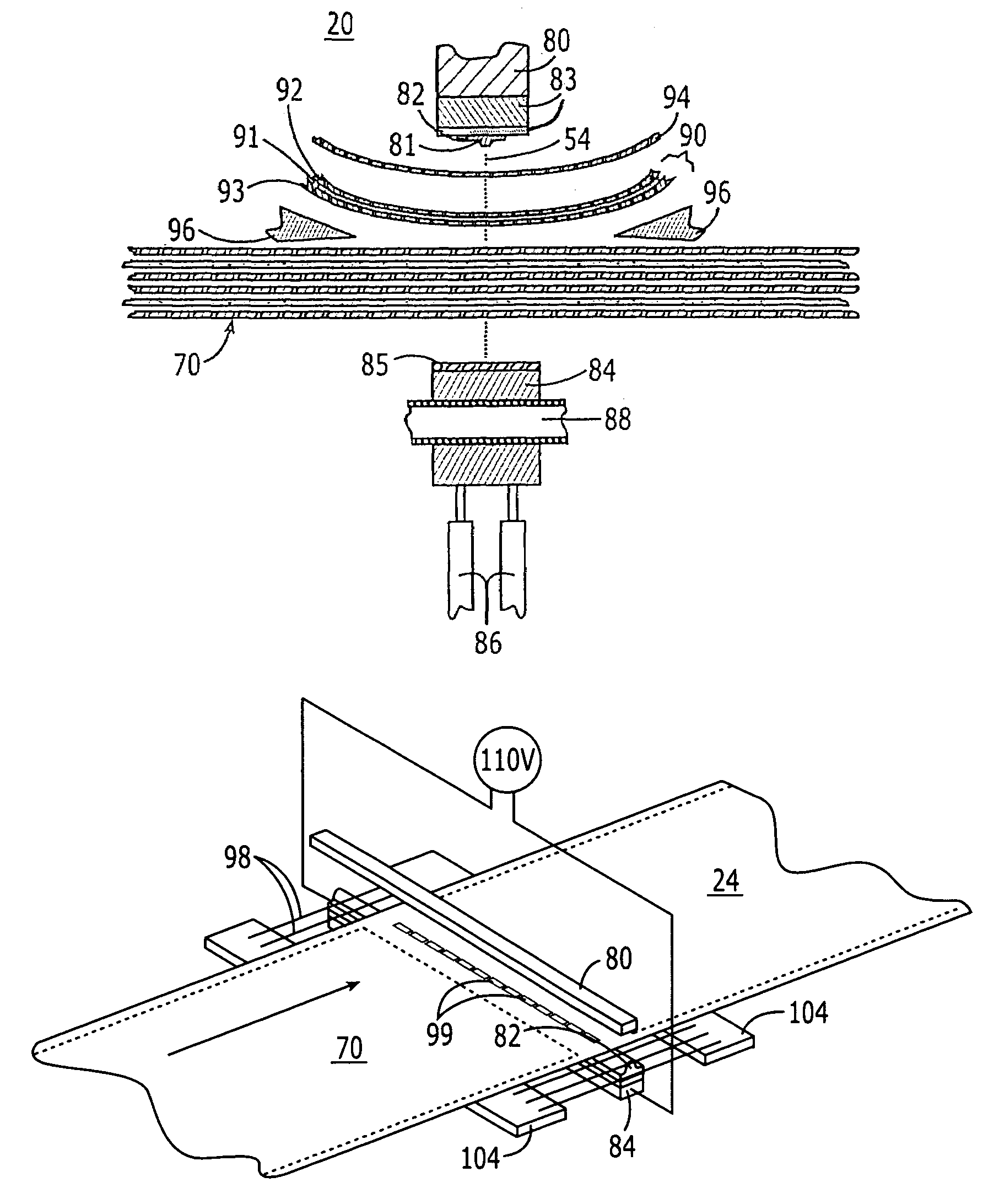
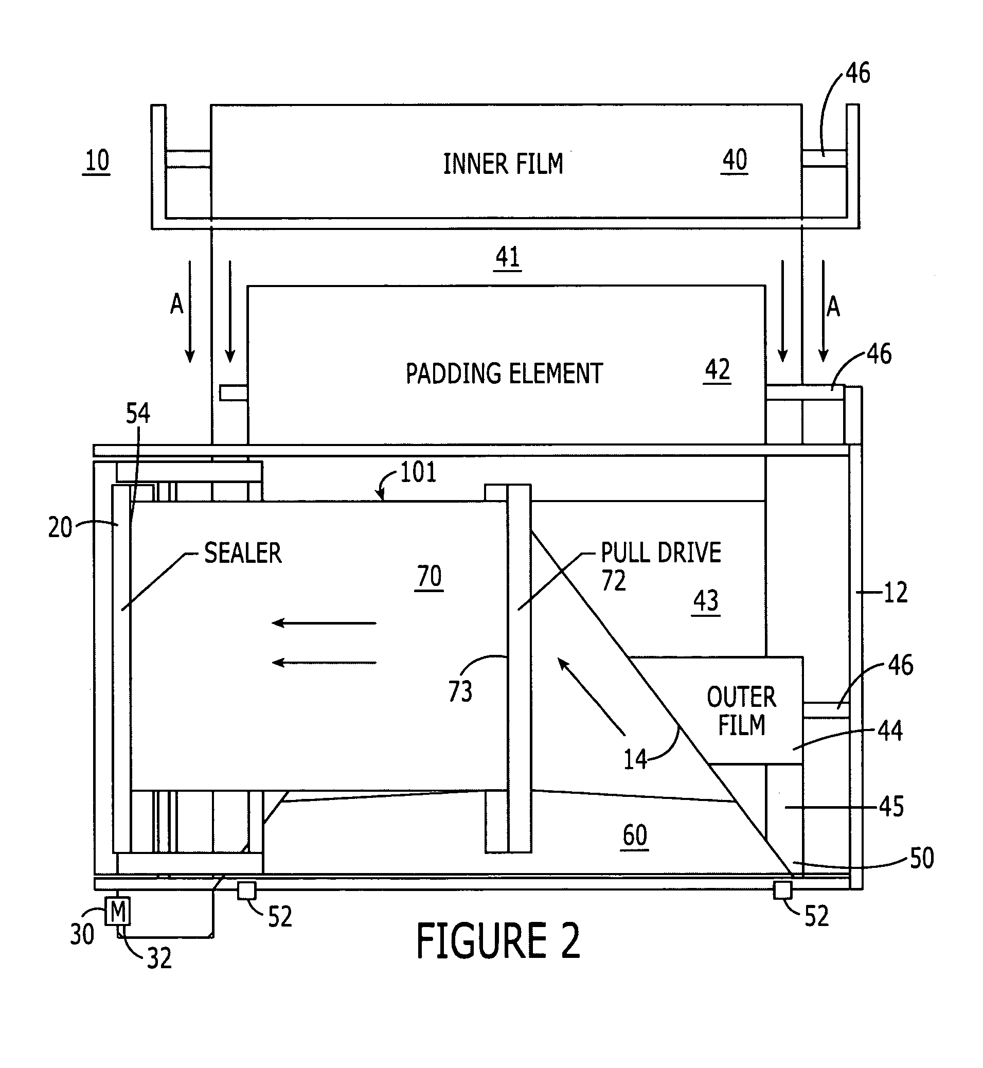
[0033]The present invention includes a method and a system for forming a series of bags having varying desired characteristics and dimensions for containing a like number of bulky articles each requiring one of the bags of varied characteristics and dimensions. Generally, the bags are to be constructed in three layers: two layers of thermoplastic film and a layer of a padding element. The film may be made of any suitable thermoplastic of any desired thickness, and the padding element may be a thermoplastic foam, a polyester pad, a synthetic fabric, or any other suitable material capable of being heat-sealed into a captured relationship with the thermoplastic film. By way of example, the present invention has been shown to be useful with a polyethylene film of 1 mil to 5 mil thickness and either a polyethylene foam of 3 / 32″ thickness or a polyester pad of 3.5-oz. weight (thickness of approximately 0.020″). However, those skilled in the art will recognize that a wide variety of materi...


PUM

PropertyMeasurementUnit
thicknessaaaaaaaaaa
initial temperatureaaaaaaaaaa
softening pointaaaaaaaaaa

Abstract

A method of forming a series of bags for bulky articles from rolled thermoplastic film and padding element includes arranging a linear, longitudinally traveling queue of layers of film and padding element according to a set of desired bag dimensions and characteristics and controlling the advancement of the queue to make padding element and seal cuts to form the bags. The invention also includes a system for fabricating bags substantially in the manner identified in the method of the present invention, as well as a method of forming seal cuts in which an envelope is first clamped, then sealed and cut by heat and pressure, then allowed to cool before being released.

Description

FIELD OF THE PRESENT INVENTION[0001]The present invention relates generally to a system and method for forming padded bags of the type typically used to package bulky articles such as pieces of furniture, and more specifically to such a system wherein bags of differing specifications, including windowed bags, may be formed on an in-line basis from a single production machine.BACKGROUND OF THE PRESENT INVENTION[0002]Bulky articles such as pieces of furniture are typically assembled at a manufacturing facility according to custom instructions based upon a customer or retailer order. Because of a wide variety of styles, constructions, fabrics, and the like within a single manufacturer's catalog, because such items are comparatively expensive, and because of traditional production practices, it is common for a furniture manufacturing facility to produce pieces of furniture of differing lengths on a piece-by-piece basis, rather than manufacturing a run of a single style all at the same t...

Claims


Application Information

Patent Timeline
Patent Type & Authority Patents(United States)
IPC IPC(8): B31B1/64B31B50/64
CPCB29C65/743B29C66/436B29C66/0044B29C66/1122B29C66/43B29C66/81427B29C66/81457B29C66/82421B29C66/91445B29C66/91921B31B19/64B31B19/74B31B19/82B31B37/00B31B41/00B65D88/1606B29C66/0042B29C66/81871B29C66/81821B29C66/91421B29C66/924B29C65/226B29C65/224B29C66/83221B29C65/00B29C66/0222B29C66/0322B29C66/8122B29C66/8511B29C2793/0045B29K2905/02B29K2905/12B29K2995/0005B29K2995/0013B29L2031/7128B31B2219/14B31B2219/23B31B2219/603B31B2219/6038B31B2219/90B31B2219/9038B31B2221/05B31B2221/10B31B2237/05B29C66/962B29C66/91651Y10S493/919B29K2827/18B29K2909/08B29C66/71B29C66/712B29C66/8181B29C66/8242B31B70/008B31B70/14B31B70/64B31B70/642B31B70/81B31B70/82B31B70/83B31B2150/00B31B2155/00B31B2160/10B31B2170/20B29K2023/06B29K2067/00
Inventor CAMPBELL, JR., ROBERT L.
Owner AUTOMATED SOLUTIONS
Why Eureka
Try Eureka