Fluorescence validation microplate and method of use

a fluorescence microplate and reader technology, applied in the field of fluorescence microplate measurement, can solve the problems of incorrect fluorescence measurement, adverse alignment, affecting the reliability of their use, etc., and achieve the effect of tight toleran

Inactive Publication Date: 2006-10-03
HUDSON GORDON S
View PDF24 Cites 15 Cited by
  • Summary
  • Abstract
  • Description
  • Claims
  • Application Information

AI Technical Summary

Benefits of technology

[0018]The entrance of any of the wells of the invention can also, in a preferred embodiment, be countersunk i.e. beveled. In a countersunk well, the well starts below the surface of the plate due to widening of the well at the surface as would be done to countersink the head of a screw. This design has at least two benefits. First, because the optics of many fluorometers are oriented at an angle, it has been discovered that the beveled edges are necessary to allow light to reach the bottom of the wells where a fluorophore is typically located. Second, it has been found that the beveled edges can be cut to minimize reflection. While black anodized aluminum can be used to manufacture a validity plate in order to reduce reflection, some small amount of the excitation light may nevertheless still bounce off the black surface into the detector, slightly raising the background. The countersinking then tends to disperse the light which bounces off the surface of the validity plate.
[0024]A fourth test provided for by the construction on the validity plate of the invention is one that tests for proper alignment of the microplate relative to the optical reading positions on the fluorometer as a measure of the alignment of the fluorometer. For this purpose, a set of wells at or near at least two edges of the microplate are each fitted with the same exact amount of fluorophore. In one embodiment, the two edges are opposite edges of the microplate (i.e. left and right or top and bottom). Deviation of the fluorescence readings of this set of wells can be attributed to alignment problems. In one embodiment, these wells are smaller than normal size well diameter, e.g. ½ standard diameter, and are positioned on opposing sides of the validity microplate, for example, in the first and last column of the microplate. In one embodiment, the entire first and last column would be wells designed to test alignment. In another embodiment, the wells are twice as deep as normal wells. Each of the wells are constructed to tight tolerances. Narrower wells and deeper wells make proper reading of the well more difficult and cause misalignment to show up easier. A properly aligned fluorometer will give essentially identical readings for each well within standard error. Misalignment will cause values to be skewed in such a manner that the misalignment can be determined. One method of evaluating the information is to calculate the slope of the values measured in column 1 and column 2 and another method is to compare the averages of column 1 to that of column 2. In another embodiment, a well in each of the four corners of the validity plate is used for alignment measurement.

Problems solved by technology

Although fluorescence microplates and fluorometers are of great utility in automated screening, there are a number of issues connected with their use that affect the reliability of their use.
Alignment is adversely affected when one or more of the aligned components involved is shifted in position or becomes damaged.
If, for any reason, the alignment is incorrect, the wells will not be centered properly, resulting in incorrect fluorescence measurements.
Cross-talk is extremely undesirable because it means the photon emissions detected, by a particular optical device at a given location originated from the sample in a different well.
In a minimum problem scenario, cross-talk only occurs from an adjacent (single) well but is still obviously undesirable.
However, these solutions do not solve all the linearity problems with fluorometers.
Another problem with the fluorometers is the necessity to select discrete wavelengths of both the excitation and emission light to measure fluorescence.
These devices are notoriously fragile, subject to damage by water, scratches, oxidation and the like causing fluorometers to give inaccurate results.

Method used


Image

  • Fluorescence validation microplate and method of use
  • Fluorescence validation microplate and method of use
  • Fluorescence validation microplate and method of use

Examples


Embodiment Construction

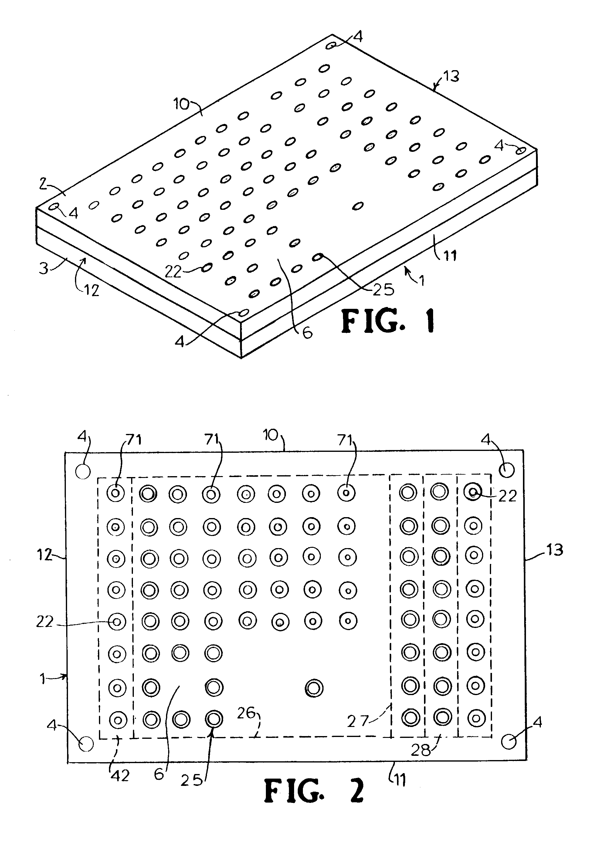
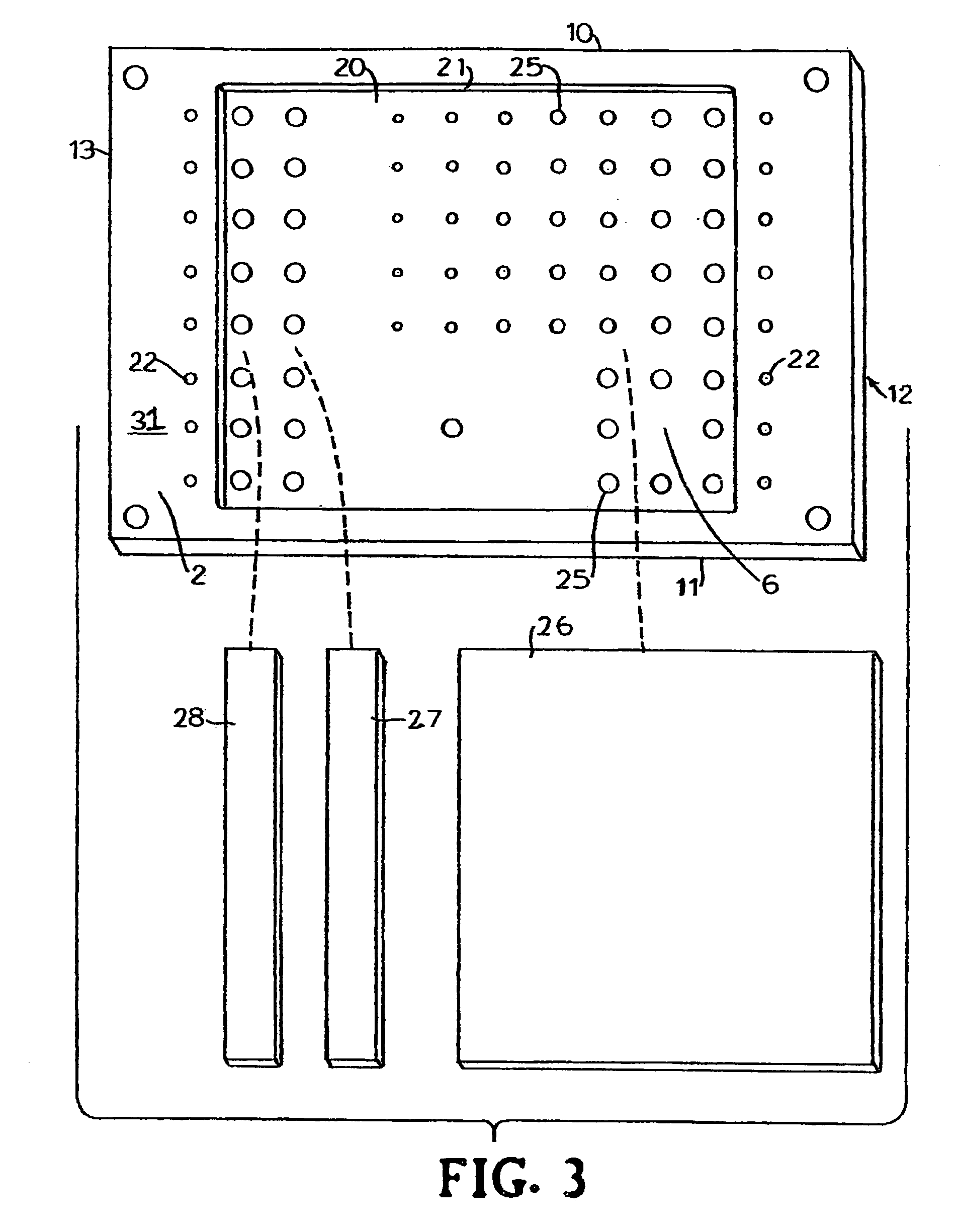
[0038]Referring to the figures, FIG. 1 is a perspective view of an embodiment of the present invention. The validity plate 1, depicted is one for testing a standard 96 position fluorometer. It consists of a top plate 2 and bottom plate 3 connected in alignment with bolts 4. The top 10 of the validity plate 1 and bottom 11 are indicated as well, as left side 12 and right side 13 of validity plate 1 for orientation are indicated.

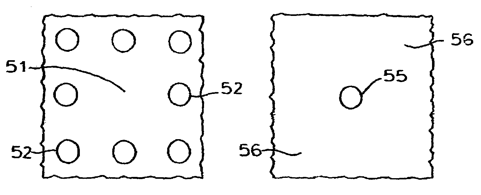
[0039]The validity plate 1 has wells 25, 22 which are of varying diameters and / or depths and are arranged such that a variety of test can be performed. Each well shown is fitted with a fluorophore. The validity plate 1 also has blanks 6 which are solid measurement positions on the validity plate 1 with no well (and thus no fluorophore). Each well 22, 25 and blank 6 corresponds to an optical reading device measurement position on the fluorometer. In an embodiment not shown, the blanks are simply empty wells with no fluorophore.

[0040]FIG. 2 is a top view of the ...


PUM

PropertyMeasurementUnit
wavelength rangeaaaaaaaaaa
diameteraaaaaaaaaa

Abstract

A fluorescence validation microplate for testing the validity of a fluorometer is provided which can efficiently and cost-effectively test fluorometers to determine linearity, alignment, reproducibility, filter integrity, and cross-talk, each of which is important to proper functioning of the fluorometer.

Description

BACKGROUND OF THE INVENTION[0001]1. Field of the Invention[0002]The present invention relates to the measurement of fluorescence by a fluorescence microplate reader. In particular, the present invention relates to a fluorescence validation microplate which is used to validate the reliability of the information received from a fluorescent assay microplate during its reading in a fluorescence microplate reader.[0003]2. Description of Related Art[0004]The growth of biological research and new pharmaceutical compound screening and in some cases, medical diagnostics has created a need for handling large numbers of test samples at one time in order to control costs and efficiently handle these large numbers of samples. A number of analytical methods are now available for high throughput screening of these samples. One of the fastest growing screening methodologies in life science is fluorescence spectroscopy. With this method, the fluorescent emission of test samples tagged with a fluores...

Claims


Application Information

Patent Timeline
Patent Type & Authority Patents(United States)
IPC IPC(8): G01N21/64B01L3/00B01L9/06G01D18/00G01N1/10G12B13/00G01N21/25G01N21/27
CPCB01L3/5085G01N21/278G01N21/6452
Inventor HUDSON, GORDON S.
Owner HUDSON GORDON S
Why Eureka
Try Eureka