Digital DLL device, digital DLL control method, and digital DLL control program

a digital dll and control method technology, applied in the direction of digital storage, pulse automatic control, instruments, etc., to achieve the effect of reducing errors

Inactive Publication Date: 2006-10-03
FUJITSU LTD
View PDF11 Cites 11 Cited by
  • Summary
  • Abstract
  • Description
  • Claims
  • Application Information

AI Technical Summary

Benefits of technology

[0021]In view of the above, the present invention has been made to solve the problems as referred to above, and has for its object to provide a digital DLL device, a digital DLL control method and a digital DLL control program which are capable of reducing an error with respect to a target amount of delay in a final output clock signal.
[0029]According to the present invention, it is possible to improve the accuracy of a delay amount in a digital DLL device with a limited increase of its circuit size and by the use of an easy control method.

Problems solved by technology

In analog DLL devices, the control signal from the delay control section 3 to the variable delay sections 1a, 1b, 1c, 1d is of an analog quantity, and hence the delay amount of each variable delay section can be adjusted steplessly, but they are vulnerable to noise since a subtle or slight change in the control signal results in a corresponding change in the delay amount.

Method used


Image

  • Digital DLL device, digital DLL control method, and digital DLL control program
  • Digital DLL device, digital DLL control method, and digital DLL control program
  • Digital DLL device, digital DLL control method, and digital DLL control program

Examples


embodiment 1

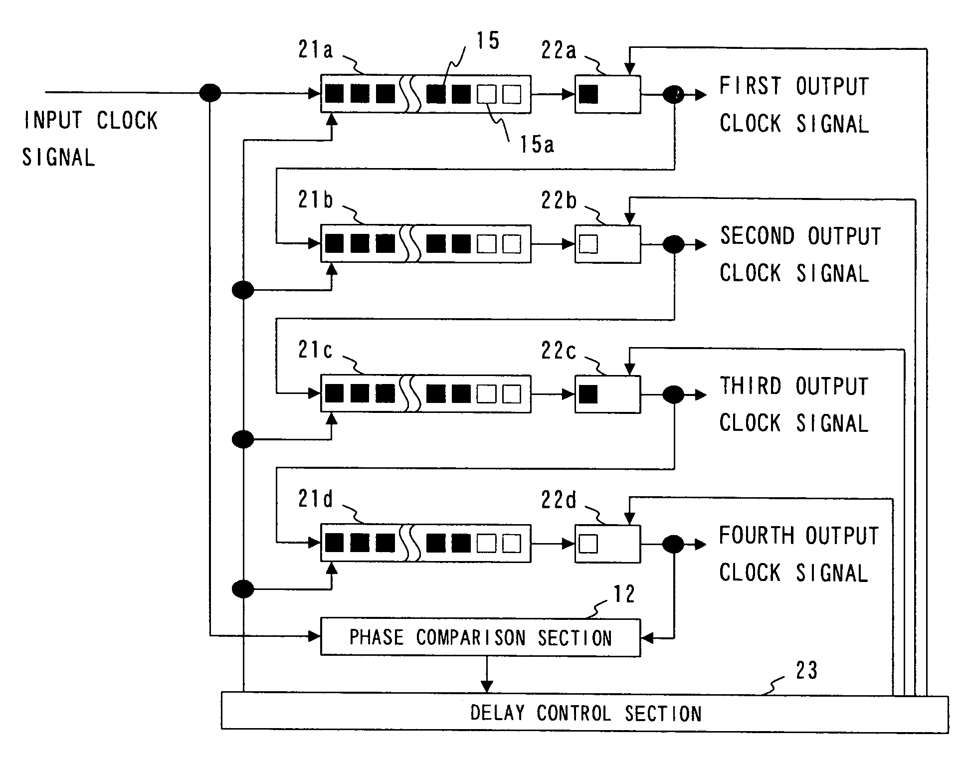
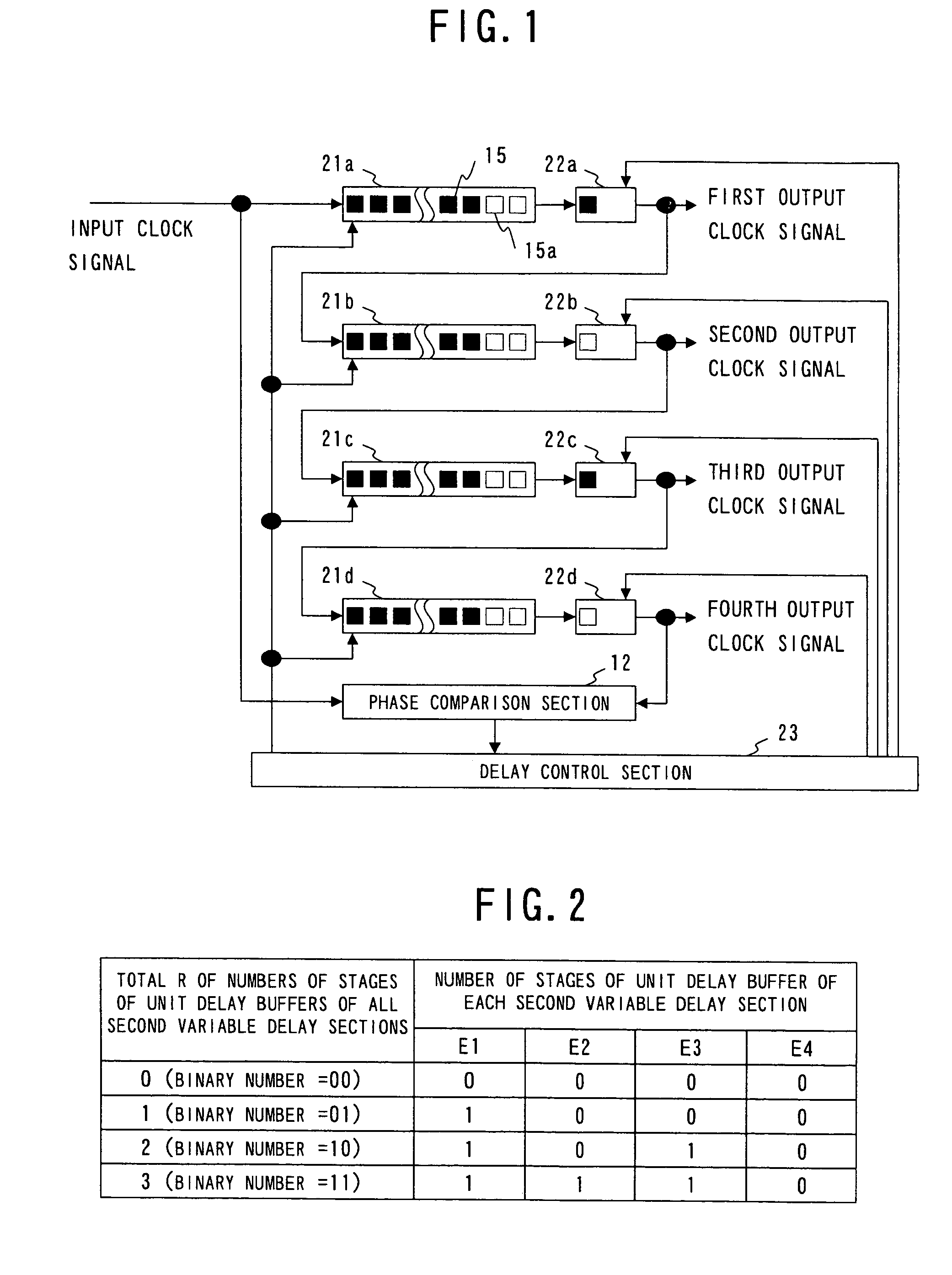
[0039]First of all, reference will be made to the construction of a digital DLL device according to a first embodiment of the present invention. FIG. 1 is a block diagram that shows one example of the construction of the digital DLL device according to the first embodiment. In FIG. 1, the same symbols as those in FIG. 7 designate the same or corresponding parts as those shown in FIG. 7, and an explanation thereof is omitted here. In this first embodiment, a delay control section 23 is provided instead of the delay control section 13 in FIG. 7. In addition, a first variable delay section 21a and a second variable delay section 22a are provided instead of the first variable delay section 11a; a first variable delay section 21b and a second variable delay section 22b are provided instead of the first variable delay section 11b; a first variable delay section 21c and a second variable delay section 22c are provided instead of the first variable delay section 11c; and a first variable de...

embodiment 2

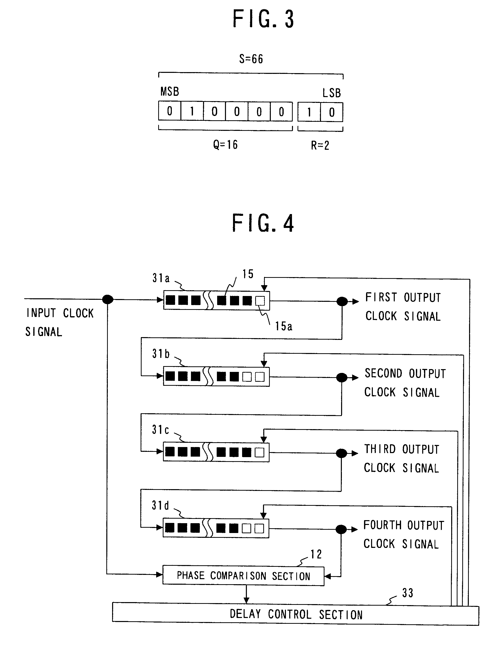
[0049]A second embodiment of the present invention is provided with only variable delay sections 31a, 31b, 31c, 31d that can control the number of stages of individual unit buffers, as in the second variable delay sections 22a, 22b, 22c, 22d of the above-mentioned first embodiment.

[0050]First, reference will be made to the construction of a digital DLL device according to the second embodiment of the present invention. FIG. 4 is a block diagram that shows one example of the construction of the digital DLL device according to the second embodiment. In FIG. 4, the same symbols as those in FIG. 7 designate the same or corresponding parts as those shown in FIG. 7, and an explanation thereof is omitted here. In this second embodiment, a delay control section 33 is provided instead of the delay control section 13 in FIG. 7. In addition, a variable delay section 31a is provided instead of the first variable delay section 11a; a variable delay section 31b is provided instead of the first va...


PUM


Abstract

A digital DLL device is provided which can reduce an error with respect to a target delay amount. The device provides a delay to an input clock signal so as to equally divide a clock cycle T thereof into N parts, and includes first variable delay sections and second variable delay sections, each of which is formed of an arbitrary number of unit delay buffers connected in series with one another. A phase comparison section makes a compare between the phase of the input clock signal and the phase of an output signal which is the input signal having been delayed while passing through all the first and second variable delay sections, and outputs a result of the comparison. A delay control section calculates a total number of unit delay buffers S required based on the phase comparison result, sets a quotient Q of S divided by N to be the number of unit delay buffers for each of the first variable delay sections, and allocates a remainder R of S divided by N to the second variable delay sections, respectively.

Description

BACKGROUND OF THE INVENTION[0001]1. Field of the Invention[0002]The present invention relates to a digital DLL device, a digital DLL control method and a digital DLL control program capable of providing a delay to an input clock signal so as to equally divide the clock cycle thereof.[0003]2. Description of the Related Art[0004]First of all, as an example of a DLL device, reference will be made to a memory interface used for DDR (Double Data Rate) memories, DDR2 memories, or the like. FIG. 5 is a timing chart showing one example of the timing of a DQS (read data strobe) signal and a DQ (read data) signal in the DDR memory interface. The DQS signal has a clock cycle T. The DQS signal and the DQ signal passed from a DDR memory to an ASIC are aligned with each other in phase at points of changes, and the DQ signal changes at an interval of T / 2. Accordingly, it is necessary to provide the DQS signal with a delay of T / 4 so as to accurately read data of the DQ signal. Thus, a DLL (Delay Lo...

Claims


Application Information

Patent Timeline
Patent Type & Authority Patents(United States)
IPC IPC(8): H03L7/06H03L7/00G11C8/00G11C11/407H03L7/08H03L7/081
CPCH03L7/0814G11C7/222G11C7/225G11C11/4076
Inventor TOKUHIRO, NORIYUKI
Owner FUJITSU LTD
Why Eureka
Try Eureka