
Layout method for improving image quality

a layout method and image quality technology, applied in the field of image layout method, can solve the problems of inapplicability of cathode ray tubes for thin and light products, affecting power consumption of more difficult to drive application specific integrated circuits, so as to improve image uniformity and reduce load difference between neighboring image input lines

Inactive Publication Date: 2006-10-03
INNOLUX CORP
View PDF8 Cites 0 Cited by
  • Summary
  • Abstract
  • Description
  • Claims
  • Application Information

AI Technical Summary

Benefits of technology

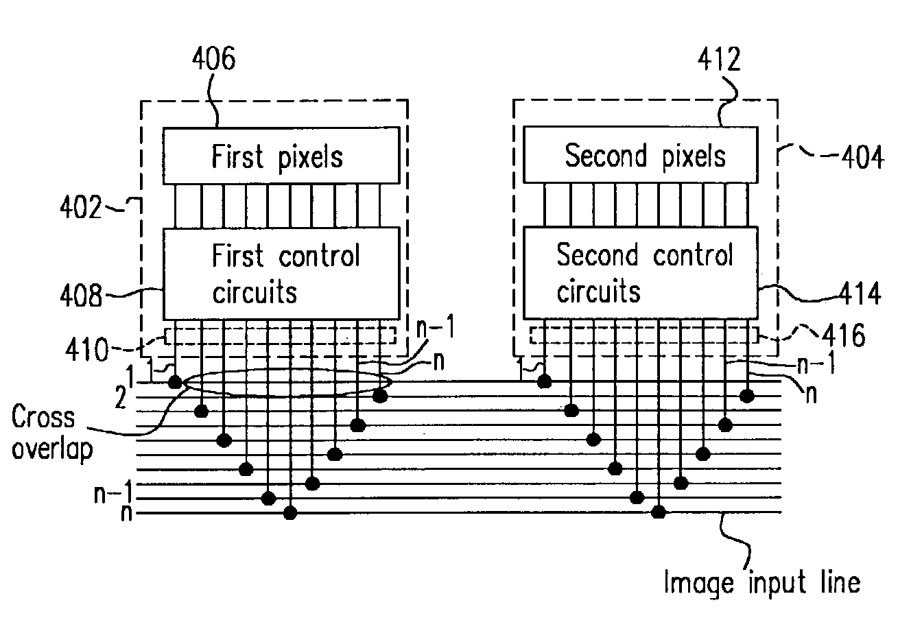
[0011]The present invention provides a layout method for improving image quality. The present invention is characterized in locating the image input line connected to the last data line in a front section in a proximity of the image input line connected to the first data line in the neighboring rear section. Therefore, the load difference between the neighboring sections is reduced, such that the uniformity of the image is improved.
[0021]According to the above, the present invention is characterized in locating another image input line connected to the first data line of the rear section in proximity of the image input line connected to the last data line of the front section. Therefore, the load difference between the neighboring image input lines is reduced, such that the image uniformity is improved.

Problems solved by technology

However, as various kinds of cathode ray tubes suffer from radiation problems, and the internal electron gun occupies such a large volume, the cathode ray tube has become inapplicable for thin and light products.
Therefore, the power consumption of the application specific integrated circuit is affected.
The larger the overlap capacitor is, the more difficult it is to drive the application specific integrated circuit.
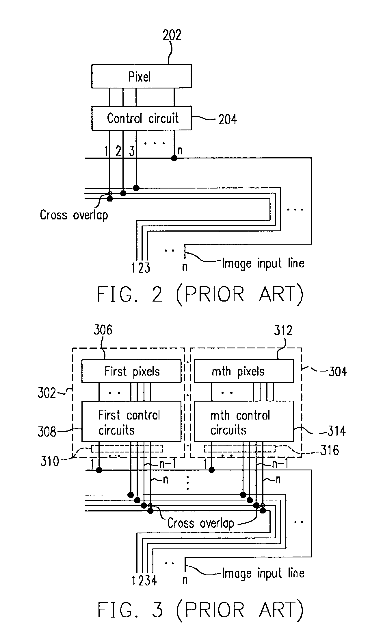
As the number of cross overlaps between the connected data lines and the image input lines varies too much, the images displayed by two neighboring sections contain a gap, seriously affecting the image quality.

Method used


Image

  • Layout method for improving image quality
  • Layout method for improving image quality
  • Layout method for improving image quality

Examples


Embodiment Construction

[0028]FIG. 4 shows a layout for improving image quality according to one embodiment of the present invention. The layout can be applied to a display such as a low-temperature polysilicon thin-film transistor liquid crystal display or amorphous silicon thin-film transistor liquid crystal display. In FIG. 4, there are n image input lines connected to the application specific integrated circuits, while the display comprises a plurality of pixels and control circuits.

[0029]The layout illustrated in FIG. 4 is used as an example to describe the present invention. In the layout method, the pixels 402 and the control circuits are divided into a first section 402 and a second section 404. The first section 402 comprises first pixels 406, first control circuits 408 and n (n is a positive integer) data lines 410.

[0030]Similarly, the second section 404 comprises second pixels 412, second control circuits 414 and n data lines 416. For a quarter common intermediate format, when there are n image ...


PUM


Abstract

A layout method for improving image quality, suitable for use in a display. The display has a plurality of pixels and a plurality of control circuits. The pixels and the control circuits are divided into several sections, each having a plurality of data lines connected to a plurality of image input lines. The layout method is characterized in that between two consecutive sections, the image input line connected to the last data line of the front section is located in proximity of the data line connected to the image input line connected to the first data line of the rear section. Therefore, loads applied to the image input lines of the consecutive sections are not too much different from each other, and the image non-uniformity is thus improved.

Description

CROSS REFERENCE TO RELATED APPLICATIONS[0001]This application claims the priority benefit of Taiwan application serial no. 92100218, filed Jan. 7, 2003.BACKGROUND OF INVENTION[0002]1. Field of the Invention[0003]The present invention relates in general to an image layout method, and more particularly, to a layout method image quality.[0004]2. Description of the Related Art[0005]The earliest dynamic image visible to human beings was the documentary movie. With the invention of the cathode ray tube (CRT), commercial television has become a necessary home appliance. The development of science and technology has further extended the application of the cathode ray tube into the desktop monitor of the computer industry for the last several decades. However, as various kinds of cathode ray tubes suffer from radiation problems, and the internal electron gun occupies such a large volume, the cathode ray tube has become inapplicable for thin and light products.[0006]The above problems thus in...

Claims


Application Information

Patent Timeline
Patent Type & Authority Patents(United States)
IPC IPC(8): G09G3/36G09G3/20
CPCG09G3/20G09G2300/0426G09G2310/0275
Inventor CHIU, CHAUNG-MINGCHUNG, MING-DA
Owner INNOLUX CORP
Learn More