Laser apparatus

a laser and apparatus technology, applied in the direction of laser details, electrical apparatus, semiconductor lasers, etc., can solve the problems of reducing the reliability of the whole reducing the reliability of the plurality of ld modules, and requiring more exacting precision of the flow path shape, etc., to achieve the effect of enhancing reliability, reducing the number of pipe members, and reducing costs

Active Publication Date: 2020-10-15
FANUC LTD
View PDF0 Cites 1 Cited by
  • Summary
  • Abstract
  • Description
  • Claims
  • Application Information

AI Technical Summary

Benefits of technology

[0022]As a method for reducing the difference of the life and the reliability between the plurality of LD modules without hardly increasing the cost, a method for switching the flow direction of the cooling liquid is conceivable. However, in this method, if the timing for switching the flow direction of the cooling liquid is inappropriate, the effect of mitigating the difference of the life load between the LD modules will be decreased. In the case where the above-described prior art for switching the flow direction of the cooling liquid is applied to the laser apparatus comprising a plurality of LD modules, there are problems that switching of the flow direction of the cooling liquid is performed frequently even during driving of the LD modules, and the effect of mitigating the difference of the life load between the LD modules is small due to inability to handle various changes in the driving conditions of the LD module.
[0054]According to one aspect of the laser apparatus, the difference of the life load between the LD modules can be effectively reduced by switching the flow direction of the cooling liquid for cooling the plurality of LD modules with an appropriate timing even when the driving condition of the LD module changes differently.

Problems solved by technology

A problem thereby arises that the life and the reliability of the whole of the plurality of LD modules are limited by the life and the reliability of the LD module arranged in the vicinity of the downstream side pipe.
However, in practice, if the cooling liquid having the same flow rate flows through the cooling liquid flow path in the vicinity of each LD module, and if the realization of cooling performance is sought with a cooling liquid flow rate equivalent to or more than the cooling performance where the cooling liquid flows through the cooling liquid flow path in the vicinity of each LD module in series, the structure of the flow path becomes complicated and the shape of the flow path requires more exacting precision.
In addition, as another method, a method for increasing the flow rate of the cooling liquid is not enough as a desirable solution because this increases the cost including the cooling liquid supply apparatus.
However, in this method, if the timing for switching the flow direction of the cooling liquid is inappropriate, the effect of mitigating the difference of the life load between the LD modules will be decreased.
In the case where the above-described prior art for switching the flow direction of the cooling liquid is applied to the laser apparatus comprising a plurality of LD modules, there are problems that switching of the flow direction of the cooling liquid is performed frequently even during driving of the LD modules, and the effect of mitigating the difference of the life load between the LD modules is small due to inability to handle various changes in the driving conditions of the LD module.
Therefore, in the field of the laser apparatus comprising the plurality of LD modules, there is a challenge to make it possible to reduce the difference of the life load between the LD modules effectively without hardly increasing the cost, and even when the driving condition of the LD module changes differently.

Method used


Image

  • Laser apparatus
  • Laser apparatus
  • Laser apparatus

Examples


first embodiment

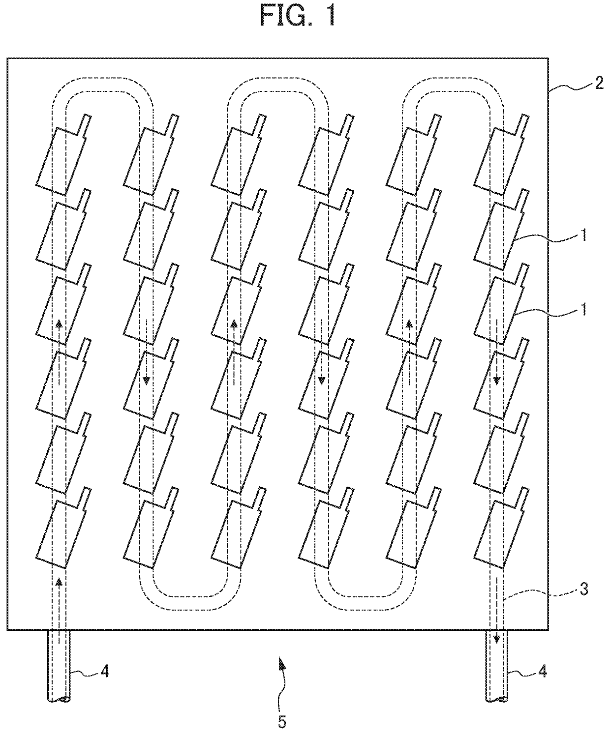
[0074]FIG. 4 is a block diagram illustrating a conceptual structure of a laser apparatus according to a first embodiment, in which an LD module / cooling plate assembly which is a portion related to cooling of the LD module is represented in a plan view illustrating a schematic structure. A laser apparatus 6A comprises a plurality of laser diode modules (LD modules) 1 on the surface of a cooling plate 2 of an LD module / cooling plate assembly 5. The plurality of LD modules 1 is disposed with the cooling plate 2 thermally connected. A driving current is supplied to the plurality of LD modules 1 in series.

[0075]Within the cooling plate 2, a cooling liquid flow path 3 is formed shown by a broken line in FIG. 4. To the cooling liquid flow path 3, a cooling liquid is supplied from a cooling liquid supply apparatus 7. The cooling liquid flows from the cooling liquid supply apparatus 7 to the cooling liquid flow path 3 formed in the cooling plate 2 via a cooling liquid pipe 4. The cooling liq...

second embodiment

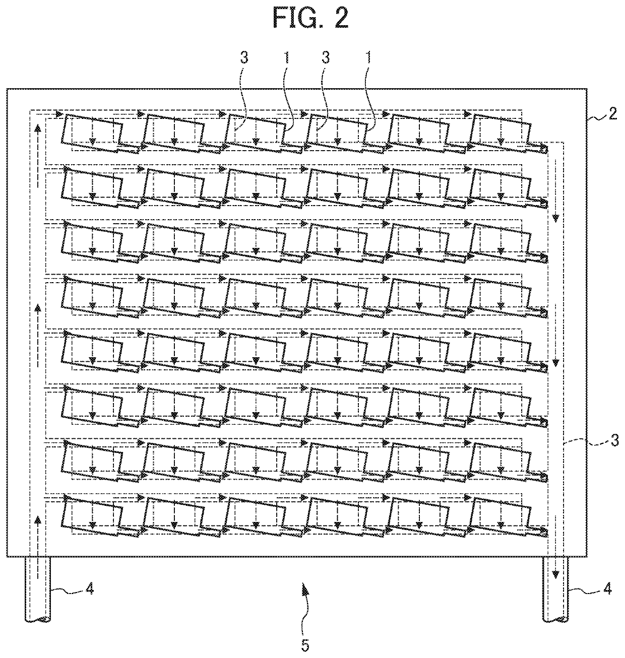
[0108]FIG. 9 is a block diagram showing a conceptual structure of a laser apparatus according to a second embodiment. As in FIG. 4 of the first embodiment, the LD module / cooling plate assembly 5 which is a portion related to cooling of the LD module 1 is represented in a plan view showing a schematic structure. As in FIG. 4, the cooling liquid flow path 3 in the cooling plate 2 is represented by a broken line. In addition, although a thick solid line arrow connecting between respective functional blocks and the like shows an output direction in communication, a supply direction of the driving current and the like, in order to avoid the complex diagram, an arrow which represents the driving current supply from the laser power source 8 to the plurality of LD modules 1 only shows an arrow from the laser power source 8 to one LD module 1 which is arranged in the farthest edge, and a line or the like showing cabling between the LD modules 1 is omitted. Also, representation of laser optic...

third embodiment

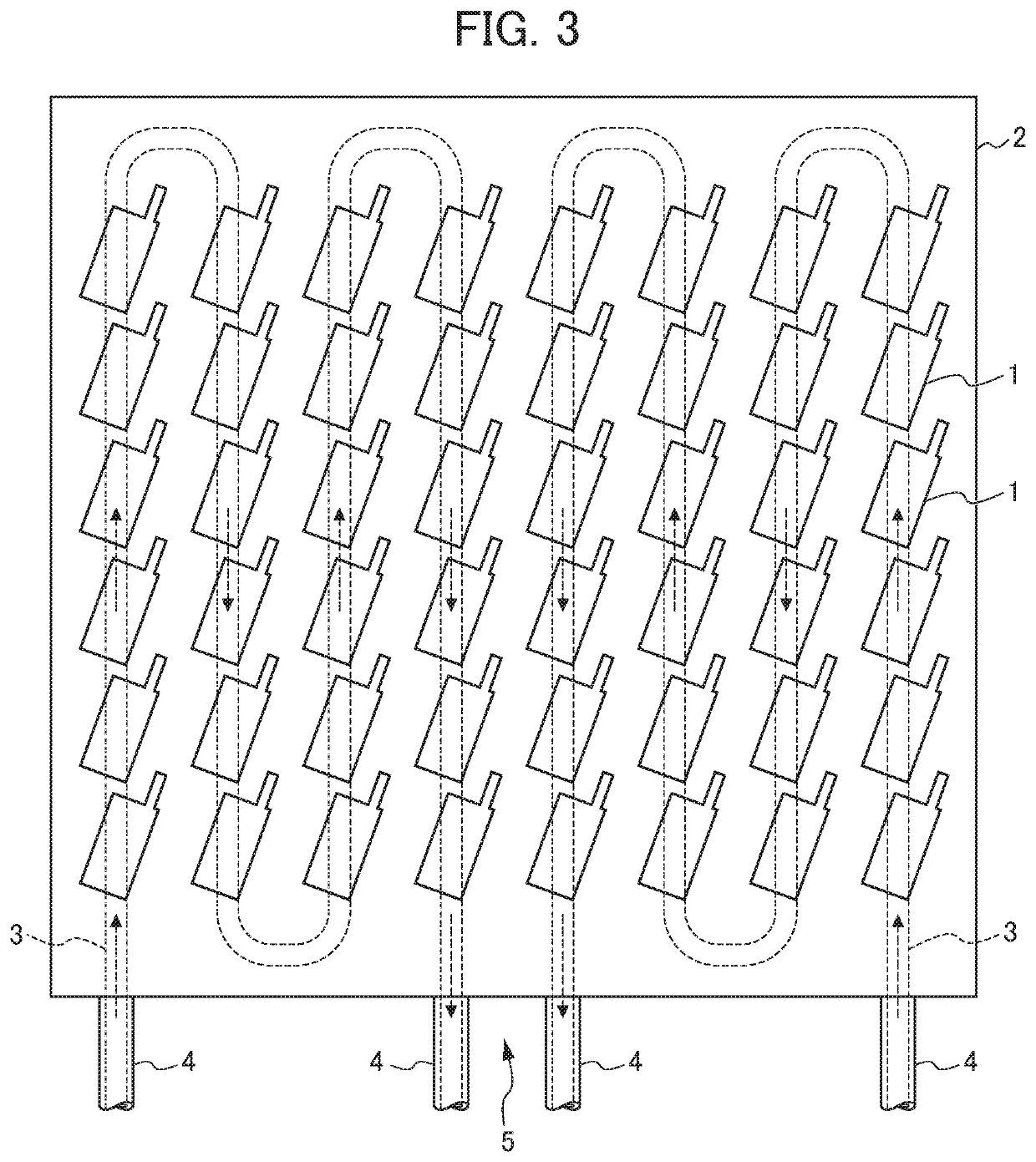
[0126]FIG. 12 is a block diagram showing a conceptual structure of a laser apparatus according to a third embodiment. As in FIG. 4 of the first embodiment and FIG. 9 of the second embodiment, the LD module / cooling plate assembly 5 which is a portion related to cooling of the LD module 1 is represented in a plan view showing a schematic structure. Also, as in FIG. 4 and FIG. 9, the cooling liquid flow path 3 in the cooling plate 2 is represented by a broken line. A thick solid line arrow connecting between respective functional blocks and the like shows an output direction in communication, a supply direction of the driving current and the like. However, in order to avoid the complex diagrams, an arrow which represents the driving current supply from the laser power source 8 to the plurality of LD modules 1 only shows an arrow from the laser power source 8 to one LD module 1 which is arranged in the farthest edge, and a line or the like showing cabling between the LD modules 1 is omi...


PUM

PropertyMeasurementUnit
temperatureaaaaaaaaaa

Abstract

A laser apparatus comprising a laser diode module / cooling plate assembly in which a plurality of LD modules to which a driving current is supplied in series is disposed on the surface of a cooling plate, comprising: a laser power source; switch valves for switching a flow direction of a cooling liquid flowing through a cooling liquid flow path; a timing determination apparatus for determining the timing for switching the flow direction of the cooling liquid, by referencing temperature time series data of at least any one temperature variation part in the laser diode module / cooling plate assembly having temperature variations due to heat generated in a heat-generating part of the laser diode module; and a control circuit for outputting a driving current output command to the laser power source and outputting a valve switch command to the switch valves by referencing the determination result of the timing determination apparatus.

Description

[0001]This application is based on and claims the benefit of priority from Japanese Patent Application No. 2019-076954, filed on 15 Apr. 2019, the content of which is incorporated herein by reference.BACKGROUND OF THE INVENTIONField of the Invention[0002]The present invention relates to a laser apparatus in which a plurality of laser diode modules (hereinafter, called LD modules) used as a laser light source or an excitation light source of the laser apparatus are cooled by disposing the plurality of laser diode modules on the surface of a cooling plate which is cooled by circulating a cooling liquid therethrough.Related Art[0003]In the recent high power laser apparatuses for laser processing, providing higher power for such apparatuses has been increasingly advanced with the aim of expanding the range (of the thickness, materials and the like, for example) for a processable workpiece (a work), facilitating the processing speed, etc. In particular, the trend toward a higher power la...

Claims


Application Information

Patent Timeline
Patent Type & Authority Applications(United States)
IPC IPC(8): H01S5/024
CPCH01S5/02438H01S5/02423H01S5/042H01S5/0021H01S5/4025H01S5/02H01S5/06216H01S5/0617H01S5/06804H01S5/0612H01S5/02251
Inventor TAKIGAWA, HIROSHIYOSHIDA, HIROYUKI
Owner FANUC LTD
Why Eureka
Try Eureka