Method and apparatus for deinterlacing

a deinterlacing and apparatus technology, applied in the direction of signal generators with optical-mechanical scanning, selective content distribution, television systems, etc., can solve the problems of large quantity of signal processing for motion vector detection, inability to detect motion vectors in time, and inability to deinterlacing the effect of a large number of codes

Inactive Publication Date: 2006-10-03
PANASONIC CORP
View PDF24 Cites 75 Cited by
  • Summary
  • Abstract
  • Description
  • Claims
  • Application Information

AI Technical Summary

Benefits of technology

[0023]An object of the present invention is to provide a deinterlacing method and a deinterlacing apparatus which can generate a progressive image of a high solution for a still picture and which can generate progressive image having no degradation of the image quality for a moving picture with a small scale of a circuit structure.
[0024]Another object of the present invention is to provide a deinterlacing method and a deinterlacing apparatus which can generate an interpolation pixel at a high accuracy, even when the deinterlacing is performed by using a motion vector that is obtained by decoding a code sequence of MPEG video.
[0032]According to a seventh aspect of the present invention, in accordance with the deinterlacing method of the first aspect, in the step of changing characteristics of the filtering process, the characteristics of the filtering are changed so that the gain of components from the forward and backward fields of the deinterlacing target field is reduced as the measured quantity of the motion is increased.

Problems solved by technology

However, line flicker and line crawling is conspicuous in the interlaced scanning method due to the high intensity and enlarged screen of the television receiver.
According to this method, since the motion of the image is detected as the motion vector information, the interpolation process which almost matches the motion of the image can be performed, while the detection of the motion vector requires a massive quantity of signal processing.
However, in a case where the motion of the image is large, when the differences between the present image and the forward and backward images are simply obtained, the predicted errors may be large, and therefore, the quantity of codes may be adversely increased.
On the other hand, in the case of a moving picture, the correlation between the field for which the interpolation pixel is generated and the forward and backward fields is low, and thus, when pixels of the forward and backward fields are subjected to the filtering process to generate the interpolation pixel, degradation of the image quality may occur.
Particularly in a case where video including an oblique edge moves vertically or the like, degradation occurs; for example, the edge looks jagged.
In addition, according to the method described in Document 2, two kinds of filters, i.e., the still picture filter and the moving picture filter, are required for generating an interpolation pixel, and as a result of requiring these two kinds of filters, the circuit scale is adversely increased.
When a motion vector is used at the motion compensation in the coding, even when its detection accuracy is low, only the coding efficiency is slightly worsened and the image quality is not remarkably degraded.

Method used


Image

  • Method and apparatus for deinterlacing
  • Method and apparatus for deinterlacing
  • Method and apparatus for deinterlacing

Examples


first embodiment

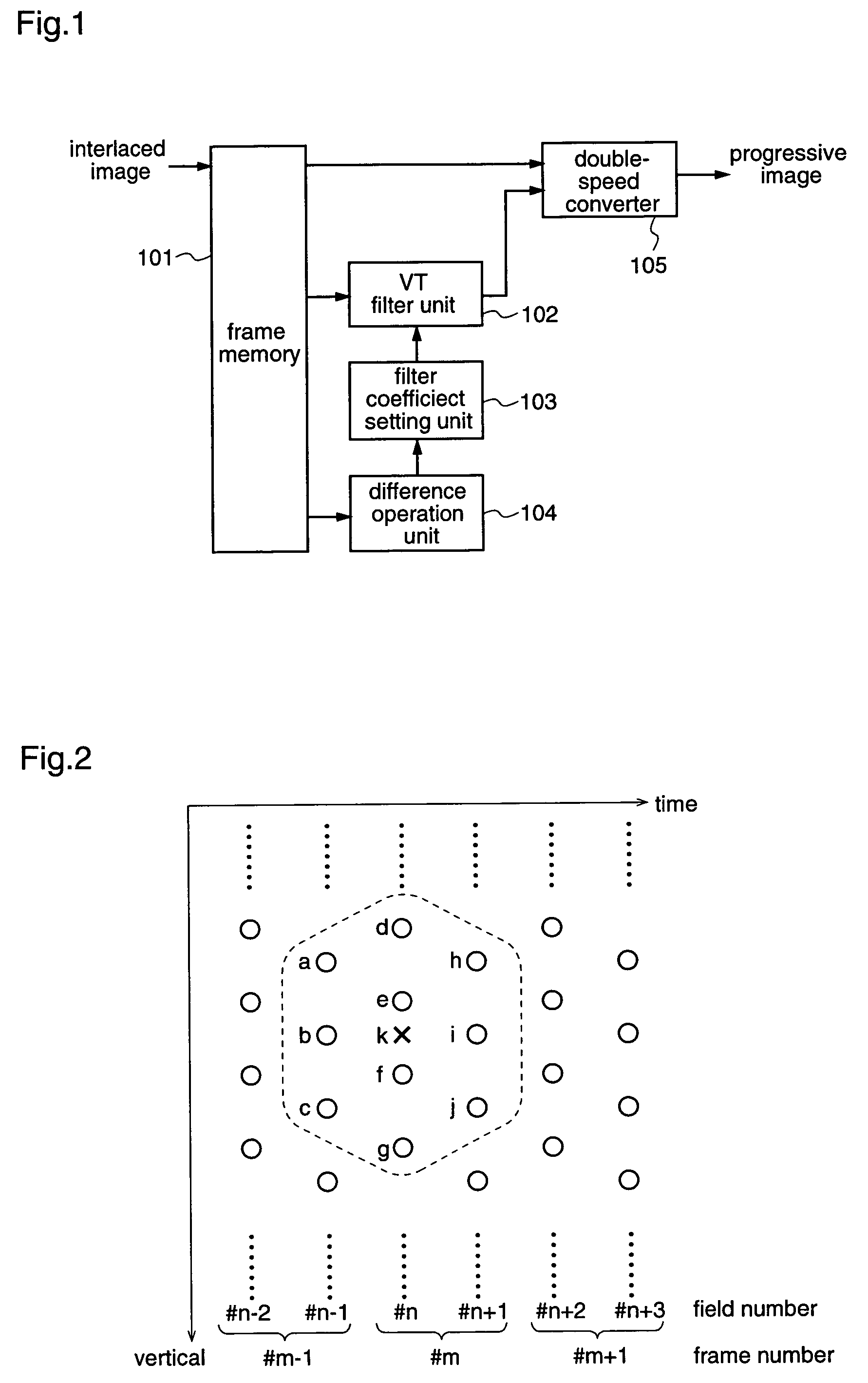
[0089]Hereinafter, a first embodiment of the present invention will be described with reference to FIGS. 1 and 2. FIG. 1 is a block diagram illustrating a deinterlacing apparatus which includes a frame memory 101, a VT filter unit 102, a filter coefficient setting unit 103, a difference operation unit 104 and a double-speed converter 105. FIG. 2 is a diagram schematically showing a state of an interlaced image on a time-vertical plane, in which a white dot shows a pixel (scan line) and white dots that are arranged in the vertical direction show pixels in the same field.

[0090]Initially, the deinterlacing apparatus stores an inputted interlaced image in the frame memory 101. Here, a description is given of a case where fields #n−2 to #n+1 as shown in FIG. 2, i.e., four fields, are stored, and the field #n is subjected to deinterlacing.

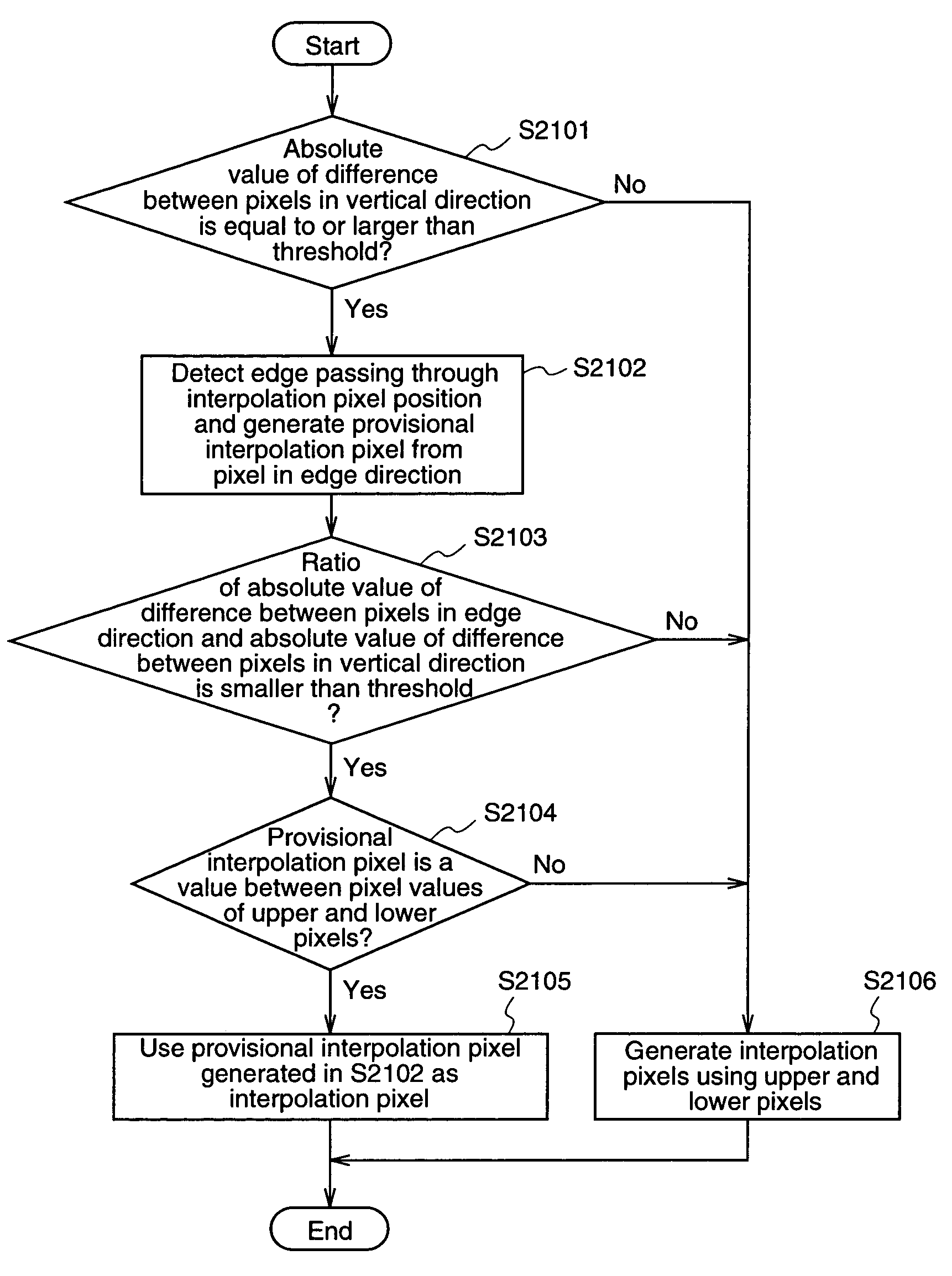
[0091]In this case, the VT filter unit 102 receives data of the fields #n−1, #n and #n+1. Then, when an interpolation pixel in a position “k” as shown i...

second embodiment

[0105]Hereinafter, a second embodiment of the present invention will be described with reference to FIG. 4. FIG. 4 is a block diagram illustrating a deinterlacing apparatus which includes a frame memory 101, a VT filter unit 102, a filter coefficient setting unit 103, a difference operation unit 404, and a double-speed converter 105.

[0106]Initially, the deinterlacing apparatus stores an inputted interlaced image into the frame memory 101. Here, a description is given of a case where three fields, i.e., fields #n−1 to #n+1 as shown in FIG. 2 are stored, and the field #n is subjected to deinterlacing.

[0107]In this case, the VT filter unit 102 receives data of the fields #n−1, #n and #n+1. Then, when an interpolation pixel in a position “k” as shown in FIG. 2 is to be generated, for example, pixels “a”–“j” as the pixels adjacent to pixel “k”, are subjected to the filtering process.

[0108]The difference operation unit 404 receives pixels “b” and “i” in the adjacent fields, which are at t...

third embodiment

[0117]Hereinafter, a third embodiment of the present invention will be described. FIG. 5 is a block diagram illustrating a structure of a deinterlacing apparatus which includes a MPEG video decoder 501 and a deinterlacer 508. MPEG video which is obtained by motion-compensating and predictive coding an interlaced image according to the MPEG method is inputted to this deinterlacing apparatus. The MPEG video decoder 501 includes a variable-length decoder 502, an inverse quantizer 503, an inverse DCT unit 504, an adder 505, a motion compensator 506, and an image memory 507. FIG. 6 is a block diagram illustrating a structure of the deinterlacer 508, which includes a parameter memory 601, a motion vector converter 602, a motion vector judgement unit 603, an inter-field interpolation pixel generator 604, an intra-field interpolation pixel generator 605, a weighting factor decision unit 606, and a progressive image generator 607.

[0118]A MPEG video code sequence which is inputted to the MPEG...


PUM


Abstract

An apparatus and method for improving the VT filter performance for moving pictures by deinterlacing. A VT filter unit receives data of a deinterlacing target field (field #n) and data of forward and backward fields of the target field (fields #n−1 and #n+1). A difference operation unit receives data of two frames including the field #n, and calculates the sum of the absolute values of differences between these frames. A filter coefficient setting unit decides a filter coefficient based on the sum of the absolute values of the differences. The VT filter unit subjects the inputted pixels to the filtering by using the filter coefficient to generate an interpolation pixel, and outputs the generated interpolation pixel. A double-speed converter composes the interlaced image and the interpolation pixel to convert the frame rate to be doubled, and outputs the converted image as a progressive image.

Description

FIELD OF THE INVENTION[0001]The present invention relates to a deinterlacing method and deinterlacing apparatus for converting an interlaced image signal into a progressive image signal.BACKGROUND OF THE INVENTION[0002]In recent years, digital processing for images has been coming into wide use. As a method for compressively coding image data, high-efficiency coding such as MPEG (Moving Picture Experts Group) has been adopted. The high-efficiency coding is a technique for coding image data at a low bit rate so as to increase the efficiency of digital transmission, recording and the like.[0003]In the current NTSC television broadcasts, an interlaced scanning method is adopted. According to the interlaced scanning method, one screen (one frame) is divided into a top field and a bottom field and is transmitted, thereby saving the bandwidth and enabling a high-efficiency transmission. However, line flicker and line crawling is conspicuous in the interlaced scanning method due to the hig...

Claims


Application Information

Patent Timeline
Patent Type & Authority Patents(United States)
IPC IPC(8): H04N7/01H04N5/44
CPCH04N7/012H04N5/4401H04N21/426
Inventor KONDO, SATOSHIITANI, TETSUYA
Owner PANASONIC CORP
Why Eureka
Try Eureka