Stereoscopic image display apparatus and stereoscopic image display system

a stereoscopic image and display apparatus technology, applied in the field of stereoscopic image display apparatus, can solve the problems of deteriorating the resolution of individual parallax images, more difficult handling in the application of tv broadcast, etc., and achieves the effect of minimizing the capacity of image data files, high resolution, and convenient handling

Inactive Publication Date: 2006-10-03
CANON KK
View PDF8 Cites 10 Cited by
  • Summary
  • Abstract
  • Description
  • Claims
  • Application Information

AI Technical Summary

Benefits of technology

[0007]It is an object of the present invention to provide a multi-view stereoscopic image display apparatus that permits the observation of parallax images from a relatively extensive range with a high resolution and minimizes the capacity of an image data file for obtaining parallax images so as to ensure easy handling.
[0008]To achieve the abovementioned object, a stereoscopic image display apparatus in accordance with the present invention includes an image display unit for displaying a plurality of pairs of images for left eye and images for right eye by using a different group of pixels for each image, and a masking member that has apertures through which light fluxes from a plurality of groups of pixels for displaying images for left eye and right eye, respectively directed to a right eye observation region (for allowing an observer to observe the image by his or her right eye) and a left eye observation region (for allowing the observer to view the image by his or her left eye), pass, and also has a light shielding portion for preventing the light from a plurality of groups of pixels from reaching a region between the two observation regions.
[0009]Thus, the light from the image display unit is intercepted so as not to reach the region which is located between the right eye observation region and the left eye observation region and in which practically no observation of an image is performed, thereby reducing the number of presented parallax images accordingly. This arrangement makes it possible to enhance the resolution of a parallax image observed from the observation region for left eye and the observation region for right eye, while securing a certain level of extension of the observation regions, and also to reduce the capacity of an image data file for obtaining parallax images.

Problems solved by technology

However, the display resolution depends on the resolution, namely, the number of pixels, of a display unit used; therefore, displaying numerous parallax images inevitably deteriorates the resolutions of the individual parallax images.
In addition, the need for preparing numerous parallax images involves an enormous capacity of an image data file, inconveniently resulting in more difficult handling in the applications for TV broadcast or the like.

Method used


Image

  • Stereoscopic image display apparatus and stereoscopic image display system
  • Stereoscopic image display apparatus and stereoscopic image display system
  • Stereoscopic image display apparatus and stereoscopic image display system

Examples


first embodiment

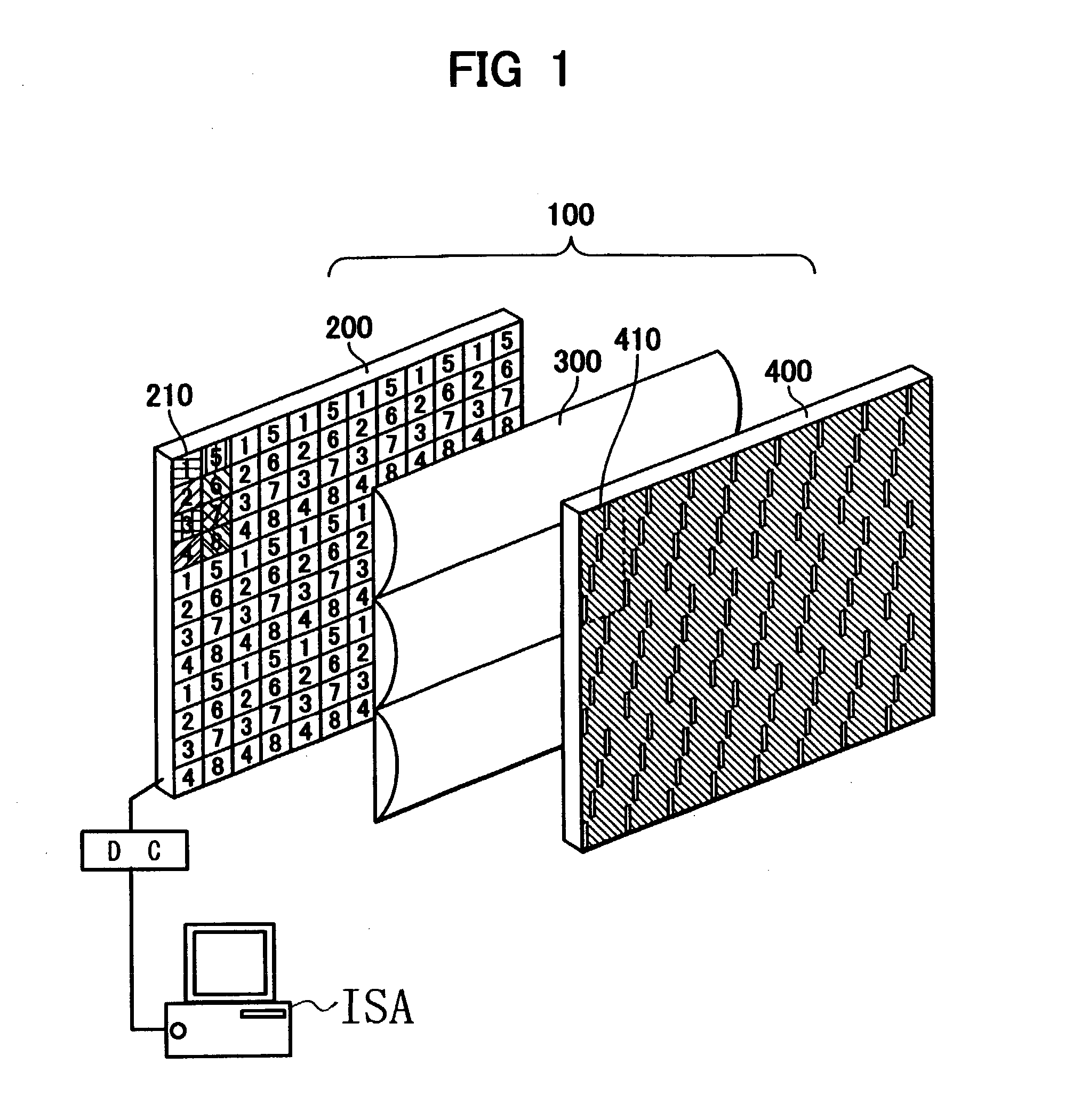
[0049]FIG. 1 shows a schematic construction of a stereoscopic image display apparatus 100 according to a first embodiment of the present invention.

(General Construction of the Stereoscopic Image Display Apparatus 100)

[0050]Referring to FIG. 1, the stereoscopic image display apparatus 100 is constructed of a display unit (image display unit) 200, a lenticular lens assembly (optical member) 300, and a mask 400.

(Display Unit 200)

[0051]The display unit 200 is constructed of a display device having pixels arranged in vertical and horizontal arrays. Typical examples include an LCD display device, a plasma display device, an organic EL display device, and a projector. A driving circuit (DC) for driving the display unit 200 receives image information from an image information supplying apparatus, such as a personal computer, video equipment, or a DVD player (ISA). The driving circuit drives the pixels of the display unit 200 on the basis of the received image information to display an image...

second embodiment

[0121]The first embodiment has referred to the case where the lenticular lens assembly 300 and the mask 400 are disposed on the display surface of the display unit 200. In this case, the display unit 200 may use a LCD display device, a plasma display device, an organic EL display device, a projector, or any other display devices in which pixels are orderly arranged in horizontal and vertical matrixes.

[0122]FIG. 17 shows a schematic construction of a stereoscopic image display apparatus 101, which is a second embodiment of the present invention.

(Three-Dimensional Image Display Apparatus 101)

[0123]Referring to FIG. 17, the stereoscopic image display apparatus 101 uses a transmissive liquid crystal device in place of the display unit 200 used in the first embodiment. The stereoscopic image display apparatus 101 is constructed of a liquid crystal display unit 201, a lenticular lens assembly 301, a mask 401 and a backlight 700. The lenticular lens assembly 301 and the mask 401 are equiva...

third embodiment

[0161]FIG. 25 illustrates the principle of the color separation taking place at an observation position when each pixel of a display unit 202 is constructed of subpixels of three colors, namely, red (R), blue (B) and green (G), and causes images constituting parallax images to be displayed for each subpixel. FIG. 25 is a sectional view showing a pixel in a 4(=p)×n−3(th) line when each pixel of the display unit 202 is constructed of three subpixels.

[0162]Referring to FIG. 25, in the display unit 202, subpixels of R, B and G making up a pixel are laterally or horizontally arranged.

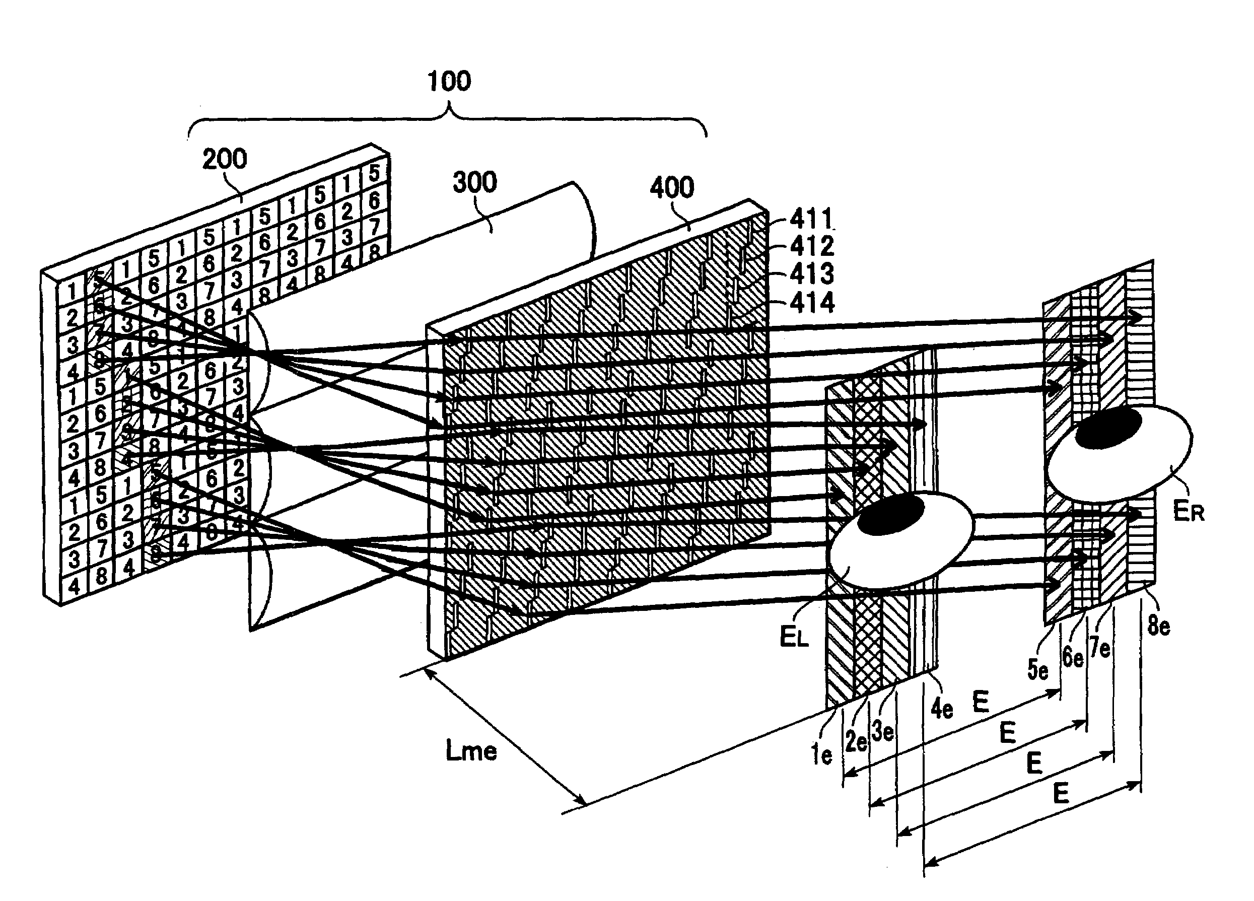
[0163]The light emitted from the subpixels constituting a pixel 1 and the subpixels constituting a pixel 5 of the display unit 202 is subjected to the action of a lenticular lens assembly 300, passes through an aperture 411 of a mask 400, and forms a left eye strip-shaped observation subregion 1e and right eye strip-shaped observation subregion 5e having a width of He in the vicinities of observation central...


PUM


Abstract

A stereoscopic image display apparatus in accordance with the present invention solves a problem with a conventional multi-view stereoscopic image display apparatus in that the resolution of each parallax image deteriorates as the number of provided parallax images increases. The inventive stereoscopic image display apparatus forms a plurality of images for right and left eyes in observation regions for the observer's right and left eyes to enable the observer to obtain a stereoscopic view. At the same time, a region where no images are formed is provided between the right eye and left eye observation regions, because no actual observation is carried out in the region. This makes it possible to reduce the total number of parallax images without changing the number of actually observed parallax images, thus achieving a higher resolution of each parallax image actually observed.

Description

BACKGROUND OF THE INVENTION[0001]1. Field of the Invention[0002]The present invention relates to a stereoscopic image display apparatus and, more particularly, to a stereoscopic image display apparatus ideally suited for performing stereoscopic display primarily in a television set, a video recorder, a computer monitor, a game machine, or the like.[0003]2. Description of the Related Art[0004]As a stereoscopic display apparatus, a “multi-view type” apparatus proposed in, for example, EP-1248473, is available. The stereoscopic image display apparatus is adapted to display numerous left eye and right eye images, i.e., parallax images, directed toward an extensive region. This means that, when an image is observed from a given position, numerous parallax images are formed also in an observable range that will not be simultaneously observed.[0005]Forming numerous images in an extensive region advantageously provides a wider observation region and permits motion parallax representation.[0...

Claims


Application Information

Patent Timeline
Patent Type & Authority Patents(United States)
IPC IPC(8): G02B27/22G02B27/00G02B30/27H04N13/04
CPCG02B27/2214G02B30/27
Inventor NISHIHARA, HIROSHISUDO, TOSHIYUKIMORISHIMA, HIDEKI
Owner CANON KK
Why Eureka
Try Eureka