Heat sink mounting apparatus

a technology for mounting apparatuses and heat sinks, applied in lighting, heating apparatuses, instruments, etc., can solve the problems of low mounting efficiency and achieve the effect of reducing the possibility of damage to components

Inactive Publication Date: 2006-10-03
HON HAI PRECISION IND CO LTD +1
View PDF5 Cites 44 Cited by
  • Summary
  • Abstract
  • Description
  • Claims
  • Application Information

AI Technical Summary

Benefits of technology

[0006]The present invention is directed to a mounting apparatus which can reduce the possibility of damaging the components to be mounted.
[0007]The present invention is also directed to a mounting apparatus which has an enhanced mounting efficiency.

Problems solved by technology

This results in a low mounting efficiency.

Method used


Image

  • Heat sink mounting apparatus
  • Heat sink mounting apparatus
  • Heat sink mounting apparatus

Examples


Embodiment Construction

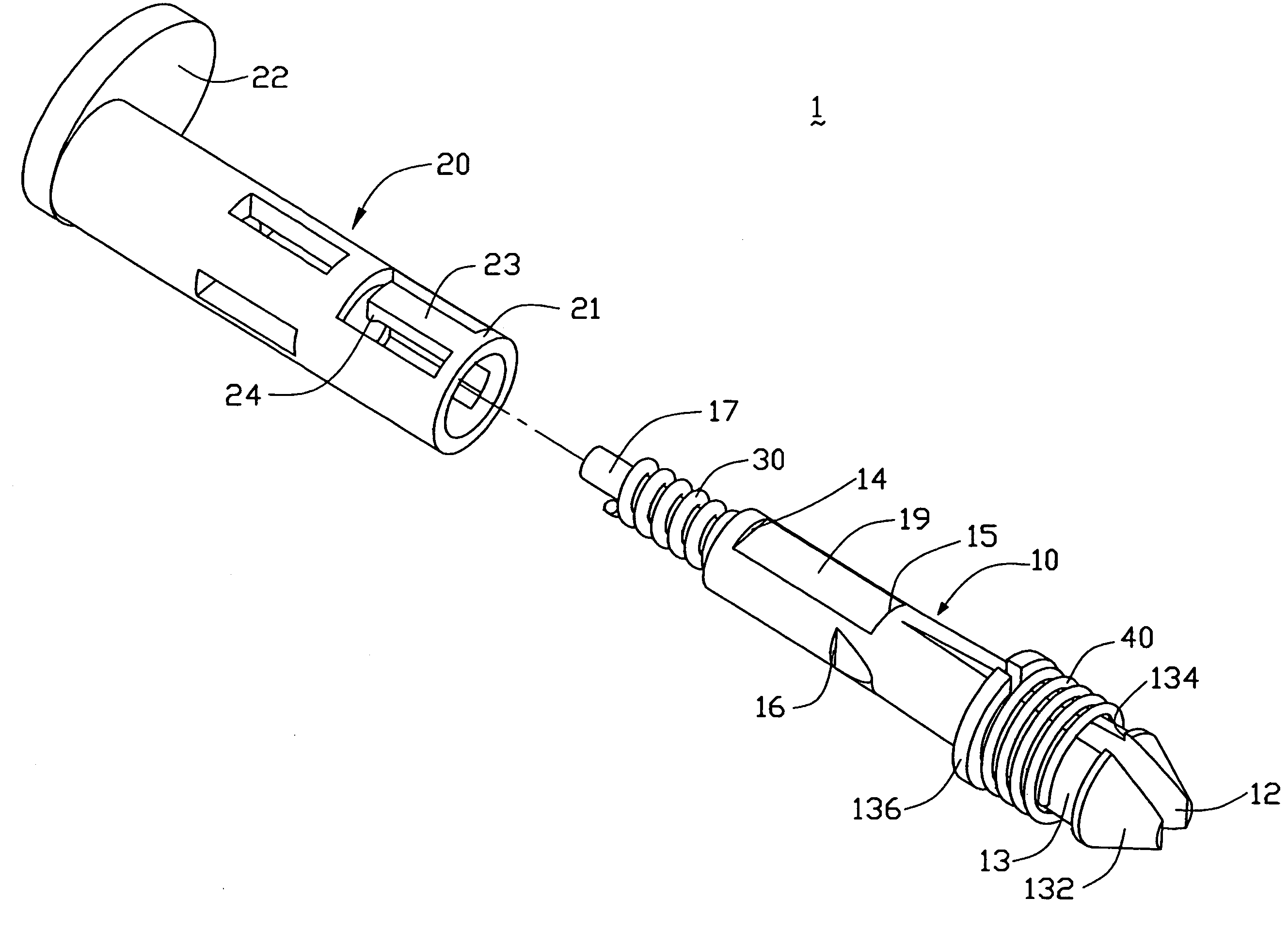
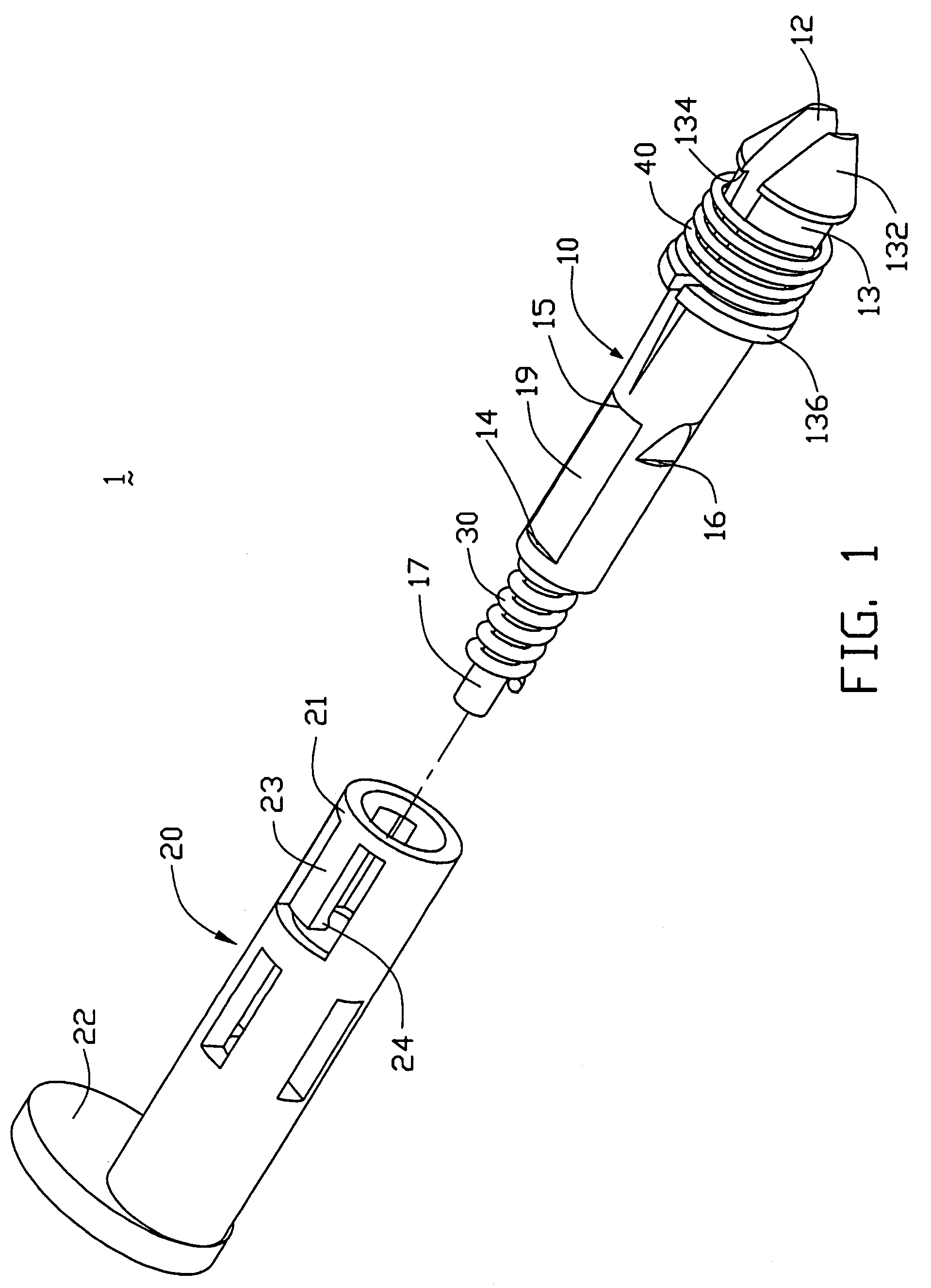
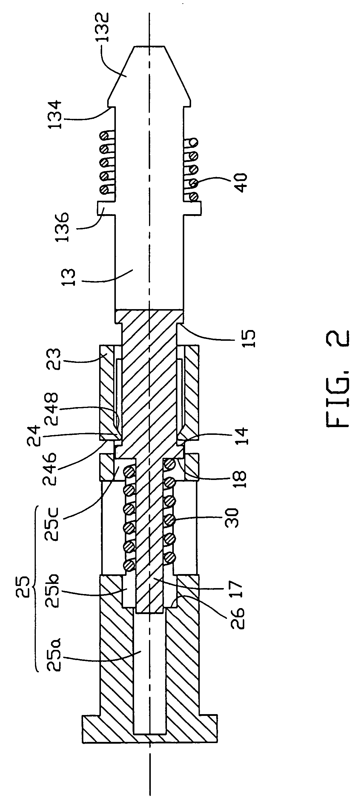
[0016]Referring to FIGS. 1 and 2, a heat sink mounting apparatus 1 according to a preferred embodiment of the present invention comprises a locking pin 10 and an operation member 20 detachably attaching to the locking pin 10.

[0017]The locking pin 10 longitudinally defines therein a slot 12 in a first end thereof. As a result, the slot 12 effectively divides the first end of the locking pin 10 into two resilient prongs 13. In normal state, the prongs 13 deform outwardly. The diameter of the locking pin 10 at the prongs 13 is greater than that at an opposite second end thereof, and the diameter of the locking pin 10 at the prongs 13 gradually increases along a first direction which points from the second end to the first end of locking pin 10. The prongs 13 can be compressed toward each other to reduce the diameter thereof, and when the compressive forces are removed, the prongs 13 can return to their original positions. Alternatively, three or more prongs 13 may be formed at the firs...


PUM


Abstract

A mounting apparatus (1) includes a locking pin (10) and an operation member (20) attaching to the locking pin. Resilient prongs (13) are formed at a first end of the locking pin. A detent (16) is formed at a periphery of the locking pin. The operation member comprises a compressing portion (21) capable of compressing the prongs radially to a predetermined compressed state when the operation member moves axially in a first direction from the second end to the first end and capable of releasing the prongs when the operation member moves axially in an opposite second direction to allow the prongs to return to their original states, and a catch (24) to engage with the detent to prevent movement of the operation member in the second direction to maintain the prongs at the predetermined compressed state.

Description

TECHNICAL FIELD[0001]The present invention relates generally to mounting apparatuses, and more particularly to an apparatus for mounting a heat sink on an electronic package mounted on a printed circuit board (PCB).BACKGROUND[0002]Mounting apparatuses for mounting two components together are often used in the industry. In the computer technology, for example, a heat sink is often disposed on an electronic package mounted on a PCB to dissipate heat generated by the electronic package. To obtain a good thermal performance, the heat sink must be secured to the PCB to enable the bottom of the heat sink to ultimately contact the electronic package.[0003]FIG. 6 shows a conventional heat sink assembly. The assembly comprises a PCB 500 with an electronic package 600 mounted thereon, and a heat sink 400 mounted on the PCB 500 by a plurality of locking pins 100. Each locking pin 100 extends through mounting holes (not shown) defined in the heat sink 400 and the PCB 500. A spring 300 is dispos...

Claims


Application Information

Patent Timeline
Patent Type & Authority Patents(United States)
IPC IPC(8): H05K7/20A41F1/00G06F1/16H01L23/40
CPCH01L23/4093H01L2924/0002Y10T24/44026Y10T24/42H01L2924/00
Inventor LEE, HSIEH-KUNCHEN, CHUN-CHIZHAO, LIANG-HUI
Owner HON HAI PRECISION IND CO LTD
Why Eureka
Try Eureka