Floating dry dock for light watercrafts

a technology for floating dry docks and watercraft, which is applied in dry docking, floating buildings, vessel construction, etc., can solve the problems of connectors falling into the water and becoming lost, damage to the floatation casings, and danger to a person walking on the dock in the vicinity

Active Publication Date: 2006-10-10
CANDOCK
View PDF26 Cites 15 Cited by
  • Summary
  • Abstract
  • Description
  • Claims
  • Application Information

AI Technical Summary

Benefits of technology

[0006]Another feature of the present invention is to provide a watercraft support platform casing for use with a floating dry dock, and wherein the floatation casings associated therewith are not impacted by the bow of a watercraft when entering the floating dry dock.
[0009]Another feature of the present invention is to provide a watercraft support platform casing rigidly connectable to floatation casings, whereby to form a drive-on floating dry dock for light-weight watercrafts such as in-board water jet propelled water crafts, making it easy for such water crafts to enter and exit the dry dock.

Problems solved by technology

There are several problems associated with such flexible docks, one of them being that when the watercraft enters the entry way, it can damage the floatation casings which are disposed in the entry way and usually disposed lower than the surface of the floatation casings to the sides of the entry way.
Because these floatation casings are formed of rigid plastic material, repetitive impact by the hull of a watercraft causes wear and tear, and the casings can become punctured and fill with water, causing the dock to sink in the forward entry way, thereby necessitating repair.
The repair consists in removing the damaged casing from adjacent casings and because there are several connectors, one at each corner of the casings, this is a time consuming job and often the connectors fall into the water and become lost.
Another disadvantage of these drive-on dry docks is that an open entrance way is formed in the dock to receive a watercraft and because the casings are pivotally secured to one another, they flex with respect to one another, and make it hazardous to a person walking on the dock in the vicinity of the entrance way.
Furthermore, these docks are constructed to support only a single watercraft and some of these watercrafts are only partly supported on the dock with the outboard engine in the rear end of the watercraft remaining in the water at the end of the dock.
This is a time consuming process for docking watercrafts, particularly when a watercraft is docked several times in a single day.
Furthermore, the bow ridge of the watercraft impacts onto smaller floatation casings disposed along a center line of the dock, and is subjected to damage, as mentioned above.

Method used


Image

  • Floating dry dock for light watercrafts
  • Floating dry dock for light watercrafts
  • Floating dry dock for light watercrafts

Examples


Embodiment Construction

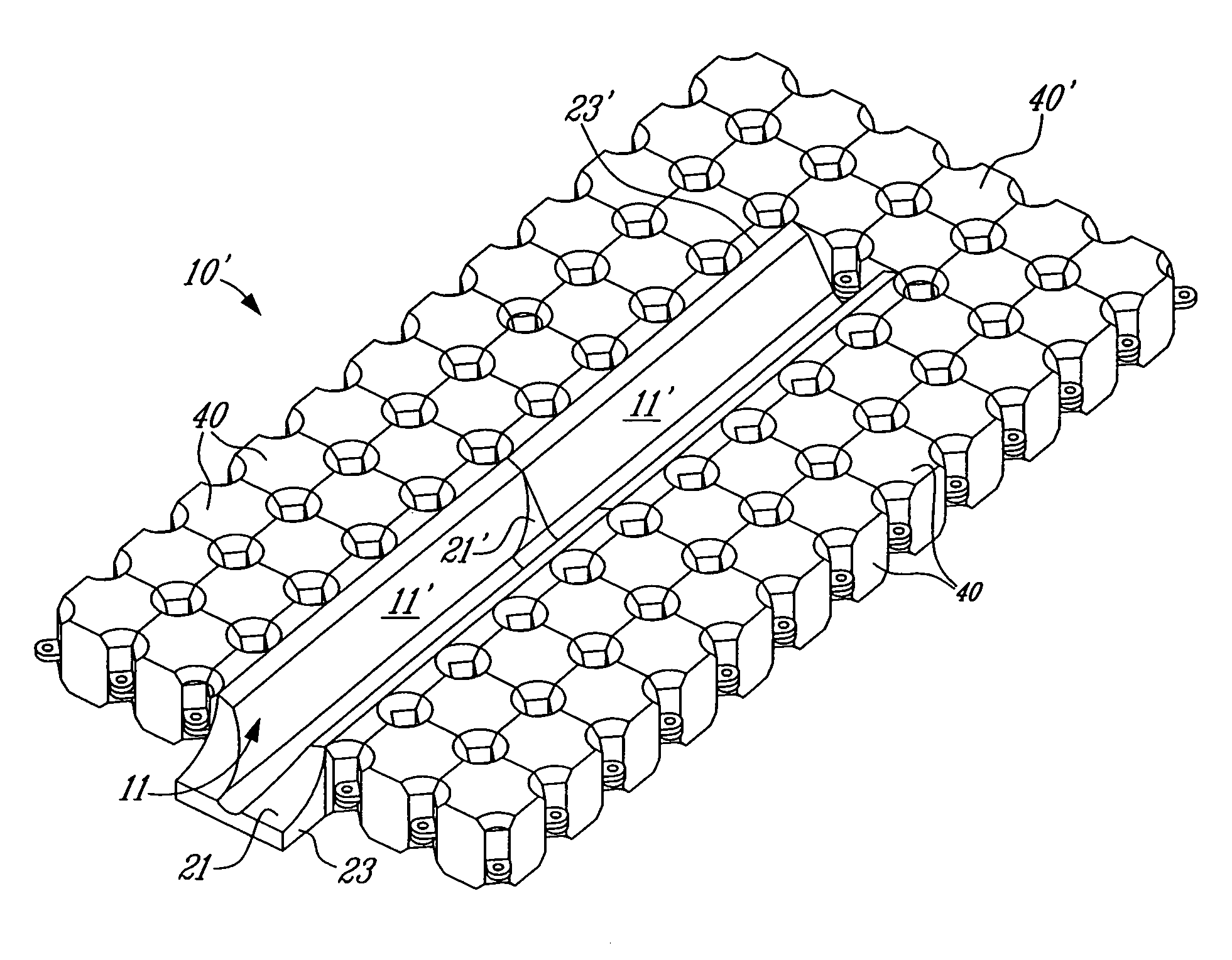
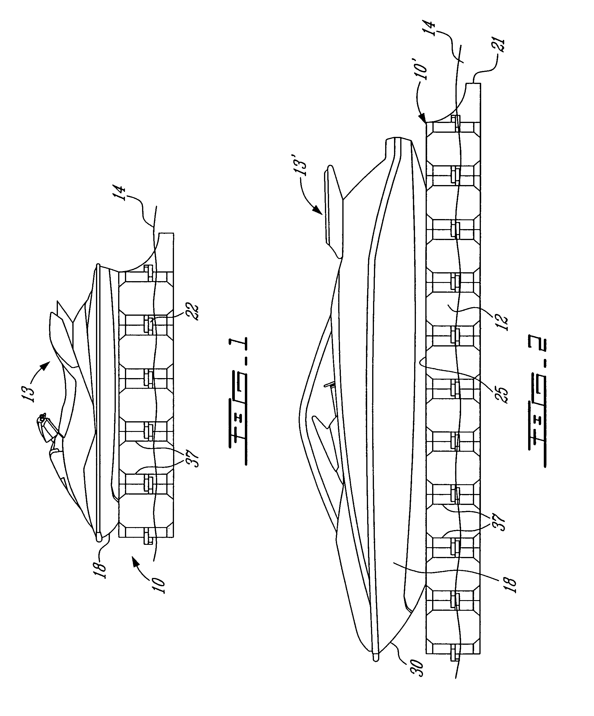
[0027]Referring to the drawings, more particularly to FIGS. 1 to 4, there is shown generally at 10 a floating dry dock constructed with the watercraft support platform casing 11 of the present invention, and rigidly interconnected with floatation casings 12. As shown in FIG. 1, the floating dry dock 10, constructed in accordance with the present invention, supports a light-weight watercraft 13 such as an inboard water jet propelled watercraft, above the water surface 14. FIG. 2 shows a larger floating dry dock 10′ constructed in accordance with the present invention, and supporting a larger watercraft 13′ above the water surface 14.

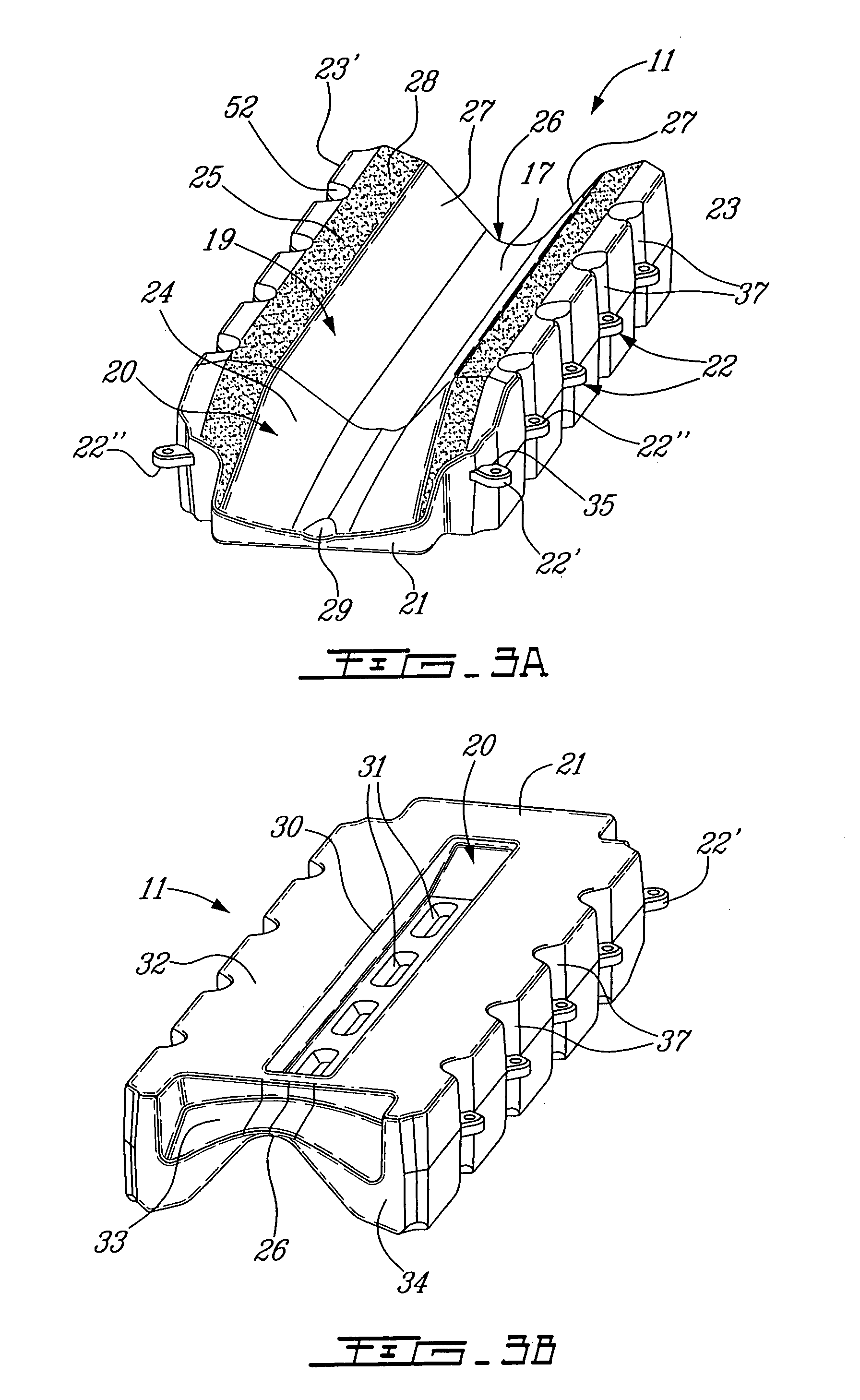
[0028]Referring more specifically to FIGS. 3A to 5, there is shown the construction of the support platform casing 11. As herein shown, the support platform casing 11 is molded from rigid plastic material, although it could be constructed of any other suitable material, and is in the shape of an elongated rectangular casing suitably dimensioned to support...


PUM


Abstract

A watercraft support platform casing for a floating dry dock for light weight watercrafts is described. The support platform casing has integrally formed floatation chambers and an elongated central ramp is formed in the top surface of the casing to support the hull of a watercraft positioned thereon. The ramp has a trough-like upper surface with a sloped forward entry way formed integral therewith and terminates in a lower forward projecting edge. The support platform is provided with connectors on opposed side walls thereof for a rigid connection with a plurality of floatation casings to support the platform casing on a water surface with the entry way positioned to receive the bow of a watercraft in movement whereby the watercraft can project itself on the central ramp above the water surface.

Description

TECHNICAL FIELD[0001]The present invention relates to a floating dry dock, and more particularly to a watercraft support platform casing which is rigidly connected to floatation casings, whereby to support a light watercraft above the water surface.BACKGROUND ART[0002]It is known to construct drive-on dry docks whereby a watercraft can enter an entry way of a floatation flexible dock and lodge itself into a channel or on smaller float casings of the dock. Such drive-on dry docks are for example described in U.S. Pat. Nos. 6,431,106, 6,526,902, 5,947,050, and 5,931,113. These dry docks comprise a plurality of floatation casings forming a dock surface on which a person can walk and an entry way in which a watercraft can enter when in motion. There are several problems associated with such flexible docks, one of them being that when the watercraft enters the entry way, it can damage the floatation casings which are disposed in the entry way and usually disposed lower than the surface o...

Claims


Application Information

Patent Timeline
Patent Type & Authority Patents(United States)
IPC IPC(8): B63C1/02B63C1/08B63C1/12
CPCB63C1/02B63C1/12B63B3/08
Inventor LAMOUREUX, SERGETREPANIER, JULIEBOURASSA, MICHELLA VIOLETTE, ERIC
Owner CANDOCK
Why Eureka
Try Eureka