Lateral thrust control

a technology of lateral thrust and control, which is applied in the direction of aircraft navigation control, rigid airships, fireworks, etc., can solve the problems of requiring an extraordinary amount of time for assembly, requiring an assembly of ignition elements and their electrical connection to the electronic control unit, and requiring an extremely time-consuming ignition element assembly and assembly, etc., to achieve easy cable breakage and installation. easy and safe

Inactive Publication Date: 2006-10-10
RHEINMETALL WAFFE MUNITION GMBH
View PDF8 Cites 9 Cited by
  • Summary
  • Abstract
  • Description
  • Claims
  • Application Information

AI Technical Summary

Benefits of technology

[0006]Known lateral thrust controls among other things have the disadvantage of requiring an extremely time-consuming assembly of the ignition elements and their electrical connection to the electronic control unit. In particular, if the lateral control comprises a large number of correction thrusters (for example, up to 180 correction thrusters), an extraordinary amount of time is required for the assembly because of the limited space conditions inside the control unit. In addition, a twisting of the individual cables during the screwing-in of the ignition elements

Problems solved by technology

Known lateral thrust controls among other things have the disadvantage of requiring an extremely time-consuming assembly of the ignition elements and their electrical connection to the electronic control unit.
In particular, if the lateral control comprises a large number of correction thrusters (for example, up to 180 correction thrusters), an extraordinary amount of time is required for the assembly because of the limited space condition

Method used


Image

  • Lateral thrust control
  • Lateral thrust control
  • Lateral thrust control

Examples


Embodiment Construction

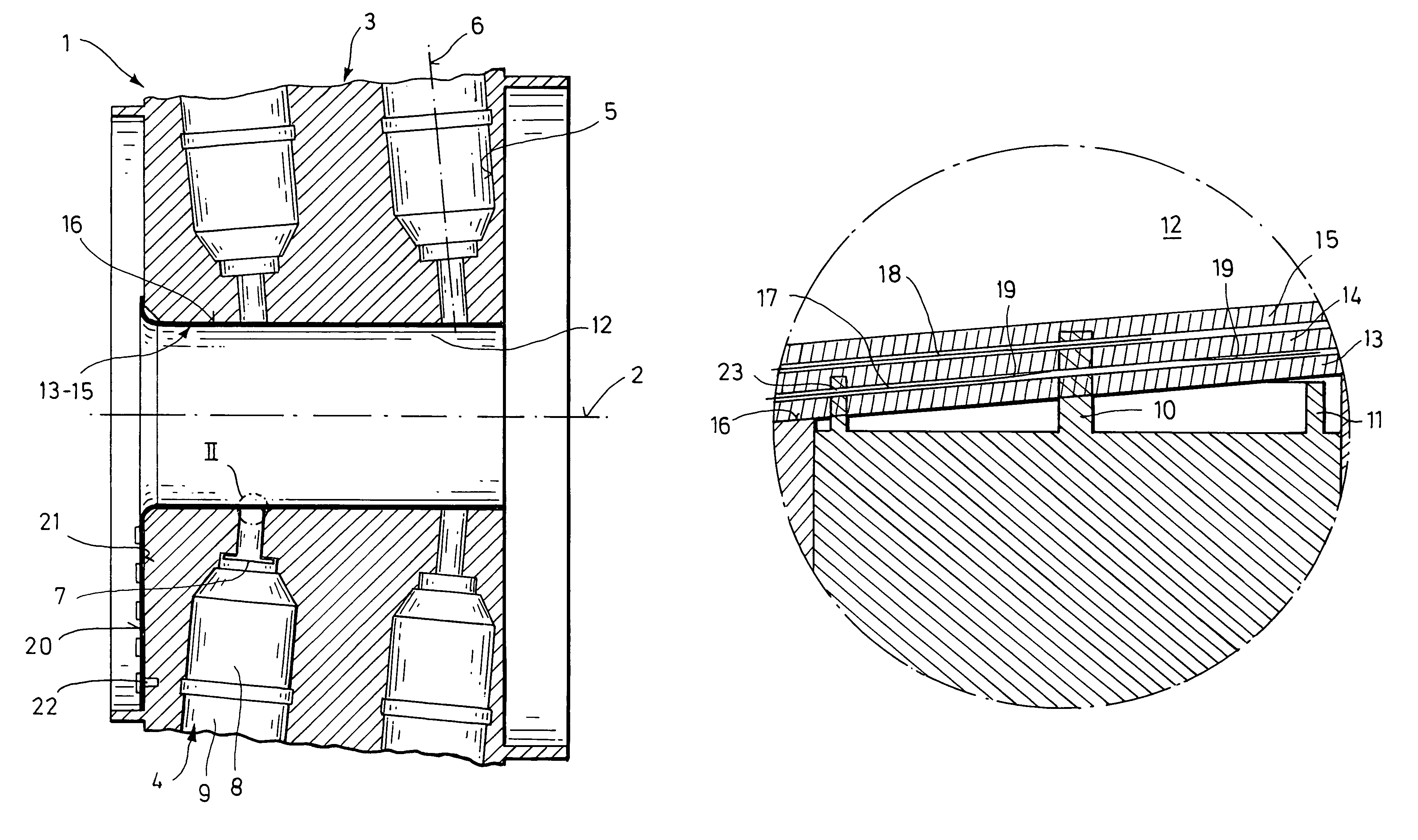
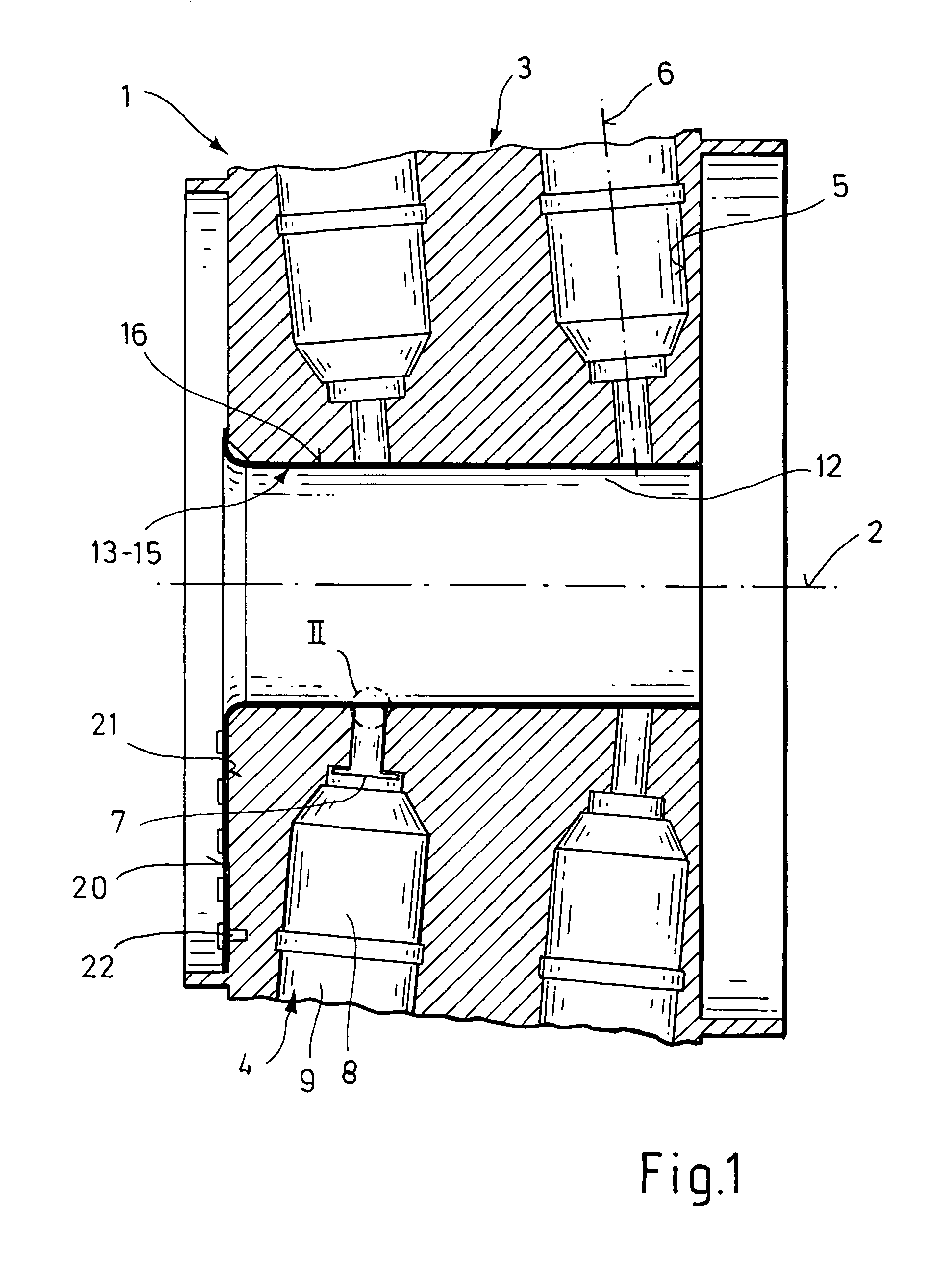
[0019]Reference number 1 in FIG. 1 refers to a lateral thrust control which can be installed, for example, in a ballistic projectile that is not shown herein. In that case, the central longitudinal axis 2 of the control 1 coincides with the longitudinal axis of the respective projectile.

[0020]The lateral thrust control 1 comprises a control unit 3 of metal with several correction thrusters 4, distributed over the periphery, which are disposed inside recesses 5. Each recess 5 has a longitudinal axis 6 that is arranged slightly slanted as compared to a radial plane that intersects with the longitudinal axis 2 of the control unit 3.

[0021]The correction thrusters 4 essentially comprise an ignition element 7 that can be screwed into the respective recess 5, a propelling charge 8, and a nozzle 9.

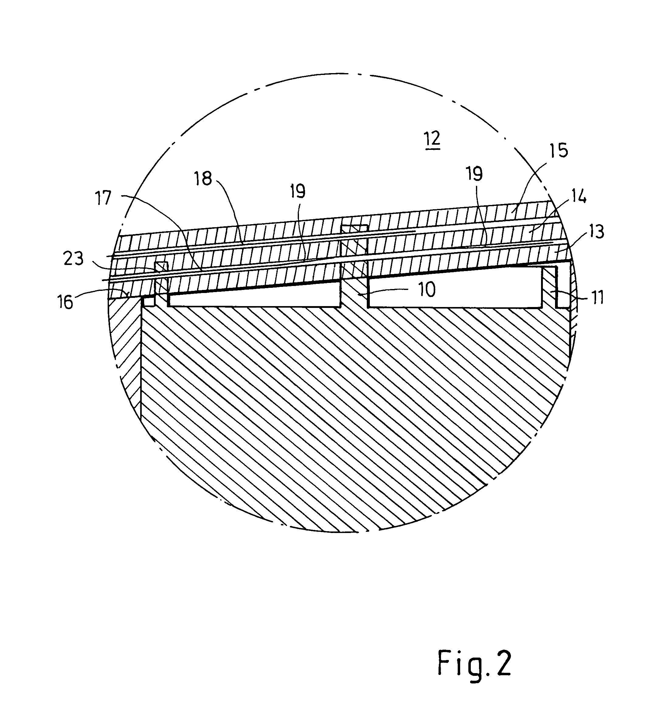
[0022]Each ignition element 7 of the exemplary embodiment shown herein has two contact elements 10 and 11 (FIG. 2), wherein the first contact element 10 is rod-shaped and the second contact elemen...


PUM


Abstract

A lateral thrust control is provided for influencing the flight trajectory of a projectile. The control has a main control unit; a central, axially extending main recess in the main control unit; a plurality of thruster recesses in the main control unit for accepting correction thrusters; an ignition element for one of the correction thrusters disposed in each of the thruster recesses; and at least one tubular conductor support of an electrically insulating material arranged inside the main recess of main control unit. At least some of the electrical conductors are in the form of conductive tracks fixedly arranged on the at least one tubular conductor support such that a particular contact element for a particular ignition element contacts the conductive track assigned to the particular contact element.

Description

CROSS REFERENCE TO RELATED APPLICATION[0001]This application claims the priority of German Patent Application, DE 103 54 098.9 filed Nov. 19, 2003, which is incorporated herein by reference.BACKGROUND OF THE INVENTION[0002]The invention relates to a lateral thrust control for influencing the flight trajectory of a projectile.SUMMARY OF THE INVENTION[0003]It is an object of the present invention to provide a lateral thrust control for influencing the flight trajectory of a projectile. The control has a main control unit having an internal surface; a central, axially extending main recess in the main control unit; a plurality of thruster recesses in the main control unit for accepting correction thrusters; an ignition element for one of the correction thrusters disposed in each of the thruster recesses, each of the ignition elements being provided with at least one contact element for connecting via a conductor to an electronic control unit; and at least one tubular conductor support ...

Claims


Application Information

Patent Timeline
IPC IPC(8): F42B15/01F42B10/66
CPCF42B10/66F42B10/661
Inventor HEITMANN, THOMASSCHWENZER, MICHAEL
Owner RHEINMETALL WAFFE MUNITION GMBH
Why Eureka
Try Eureka