Method for fixing a soft tissue on a bone

a soft tissue and bone technology, applied in the direction of nails, staples, applications, etc., can solve the problems of tissue necrosis, bone piercing, and difficult to determine the exact positioning spot,

Inactive Publication Date: 2006-10-10
MD SUPPLY S A R L
View PDF16 Cites 96 Cited by
  • Summary
  • Abstract
  • Description
  • Claims
  • Application Information

AI Technical Summary

Problems solved by technology

However, when these staples are used, there is always a metal part which protrudes from the surface of the connective tissue and which could cause tissue necrosis.
One of the major disadvantages of these screws is that the bone must be pierced in order to insert them.
Another disadvantage is that the exact positioning spot is difficult to determine.
Furthermore, by its design, the spacing between the two fixing elements is necessarily unchangeable, which makes the invention unusable for a large variety of applications.
As mentioned previously, the existence of a semi-rigid connection between the two fixing elements can cause tissue necrosis.
Finally, it is only possible to connect the two fixing elements two at a time and it is not possible to connect three or four elements, which could be necessary when there is a large attaching surface.
This type of element has the notable disadvantage that, because of its size, it destroys tissue when it is inserted.
Inserting it is therefore difficult.
The fact that the suture material is joined to the pin means that it is not possible to use suture material with which users are used to working.
So, many operations fail due to rupture of the tissue by the suture material which must be, on the one hand, sufficiently taught to hold the tissue; and, on the other hand, sufficiently flexible not to cut it.
This device, like the previous one, does not allow two anchorages to be done in one step, and there is no parallelism between two elements inserted one after the other.
Moreover, they produce a compression not adapted to the tissue surface, which could cause either necrosis or rupture in the tissue.

Method used


Image

  • Method for fixing a soft tissue on a bone
  • Method for fixing a soft tissue on a bone
  • Method for fixing a soft tissue on a bone

Examples


Embodiment Construction

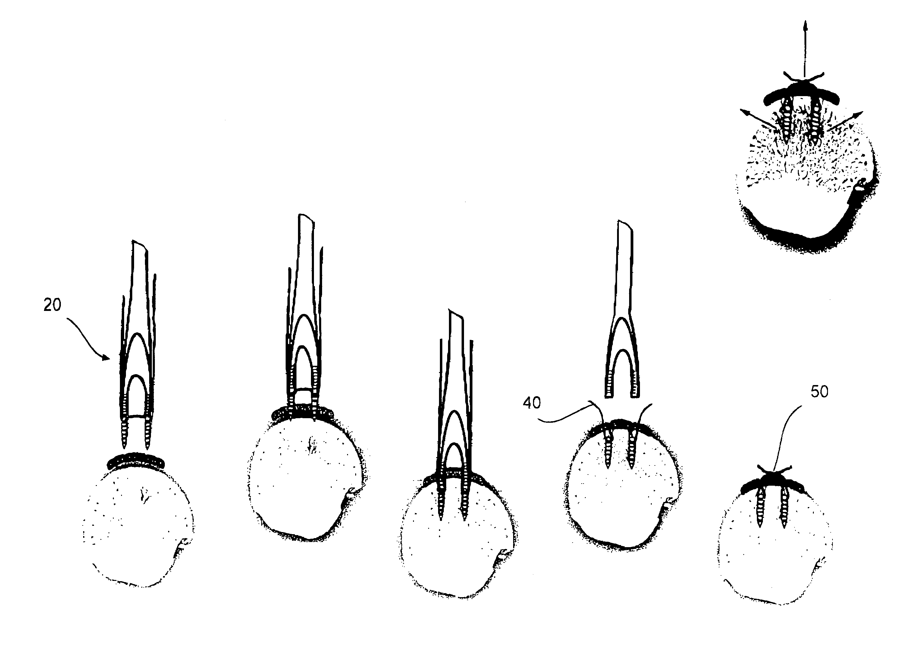
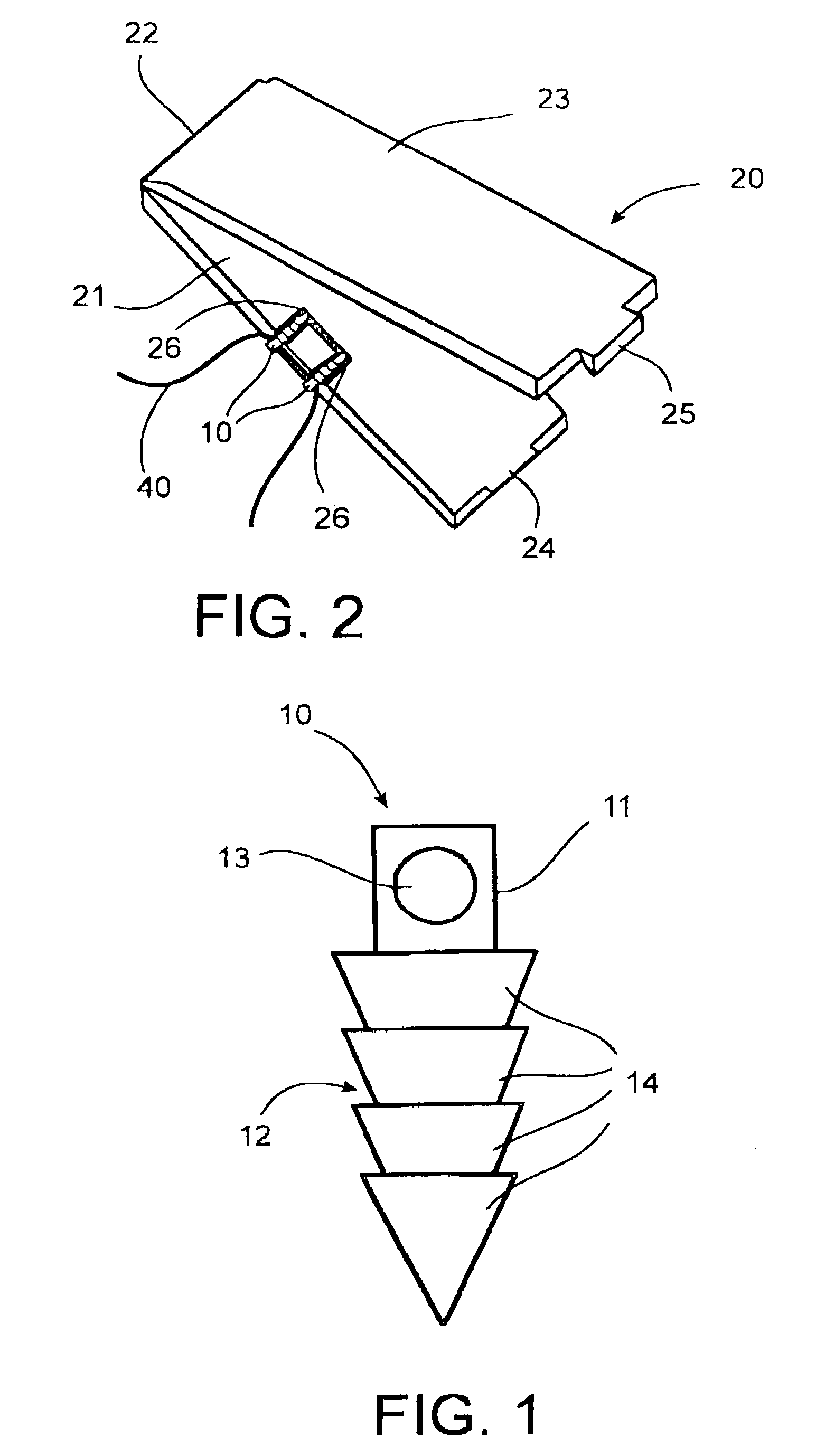
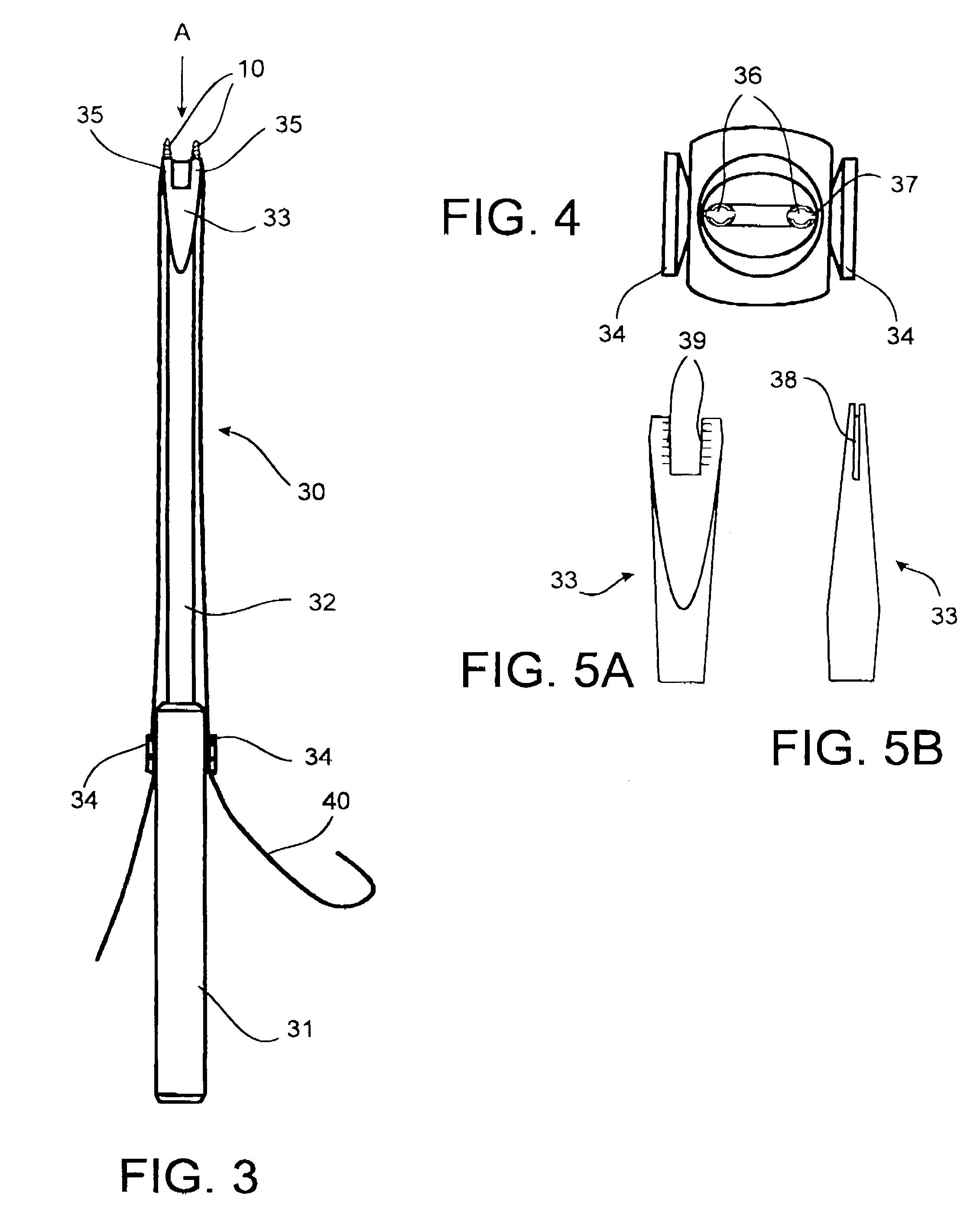
[0026]Referring to the figures, the fixing system according to the invention consists of two pins 10 for attaching a connective tissue, such as the extremity of a tendon or ligament, to a bone ridge during reparative surgery. In order to facilitate the imposition of the two pins by inserting them in the bone simultaneously with a defined space between them, as when using staples, the fixing system as illustrated by the figures has, as well, a pro-positioning element 20 for the pins 10, as well as a device to position and insert (positioning and position maintaining mechanism) 30 the pins in the superposed connective tissue and bone. When they have been put in place, the two pins are connected by a connecting means 40 made up of suture material for creating the means of maintaining in position 50 the connective tissue on the bone.

[0027]The pins 10 as illustrated by FIG. 1, and whose conical ‘pine tree’ shape has been specially designed to obtain a solid fixation, comprises a first su...


PUM


Abstract

The invention concerns a set for fixing a soft tissue, such as a ligament or tendon on a bone, comprising two nails (10) and a member for positioning and setting (30) the nails in the superimposed soft tissue and bone. The two nails comprise a first cylindrical upper portion and a second lower portion formed by a stepped coaxial superposition of inverted cones. The cylindrical portion is provided with a hole for passing through a suture (40) designed to constitute a way for maintaining the soft tissue in position on the bone during healing. The positioning and setting member (3) comprises a handle (31) wherein is nested a cylindrical rod (32) including an end (33). The U-shaped end comprises two branches (35) provided with a blind cylindrical bore designed to receive the cylindrical part of the nails (10). When the nails are secured to the member (30), the suture (40) is maintained by the stop elements (34) of the handle (31).

Description

TECHNICAL DOMAIN[0001]This invention relates to a system of fixing connective tissue, notably a ligament or tendon, to a bone by means of at least two pins, each pin comprising an upper cylindrical section and a lower section made up of superposed inverted cones with a directrix whose diameter is greater than the diameter of the cylindrical section, the fixing system including a means of connecting the two pins, some means for holding the connective tissue in position on the bone once the pins have been put in place, each pin formed so as to prevent its vertical movement in the bone after it is put in place.[0002]It relates, as well, to a procedure for fixing connective tissue, notably a ligament or a tendon, to a bone by means of at least two pins, by means of the fixing system according to the invention.PRIOR ART[0003]Ligamentous lesions are more common after multiple accidents, notably occurring in the field of sport. A ligament reconstruction is then necessary and this needs to ...

Claims


Application Information

Patent Timeline
Patent Type & Authority Patents(United States)
IPC IPC(8): A61F2/38A61B17/04A61B17/56A61F2/08
CPCA61B17/0401A61F2/0811A61B2017/0409A61B2017/0412A61B2017/0414A61B2017/0427A61F2/0805A61F2002/0858A61F2002/0888Y10S606/916
Inventor FRIDEN, PER-ANDERS
Owner MD SUPPLY S A R L
Why Eureka
Try Eureka