Radiation emitter device having an integral micro-groove lens
What is Al technical title?
Al technical title is built by PatSnap Al team. It summarizes the technical point description of the patent document.
a technology of radioemitter and micro-groove, which is applied in the direction of semiconductor/solid-state device details, fixed installation, lighting and heating apparatus, etc. it can solve the problems of unsuitable devices for certain applications, above imaging problems can also be present, and non-uniform light emission of photoluminescent materials, etc., to achieve the effect of effective illuminator/indicator devices
Inactive Publication Date: 2006-10-10
EVERLIGHT ELECTRONICS
View PDF31 Cites 14 Cited by
Summary
Abstract
Description
Claims
Application Information
AI Technical Summary
This helps you quickly interpret patents by identifying the three key elements:
Problems solved by technology
Method used
Benefits of technology
[0016]Accordingly, an opto-electronic emitter device has been designed to overcome the above problems and to provide an effective illuminator/indicator device. To achieve these and other aspects and advantages, the radiation emitter device of the present invention comprises at least two radiation emitters emitting radiation of different wavelengths, first and second ele...
Problems solved by technology
Such an arrangement is problematic in that neither LED chip 1 is disposed at the focal point or on the central axis of spherical lens surface 5.
This has the undesirable effect of magnifying and projecting an image of the LED chips at a distance from the LED device.
When the different colors from the LED chips are desired to mix so as to provide a different color, the ability of an observer to see the two different colored chips from a distance may render the device unsuitable for certain applications.
The above imaging problem also can be present when one of the radiation emitters is an LED chip and the other radiation emitter is a photoluminescent material that is in...
Method used
Image
Click on the blue label to locate the original text in one second.
Reading with bidirectional positioning of images and text.
Examples
Embodiment Construction
[0033]Reference will now be made in detail to the present preferred embodiments of the invention, examples of which are illustrated in the accompanying drawings. Wherever possible, the same reference numerals will be used throughout the drawings to refer to the same or like parts.
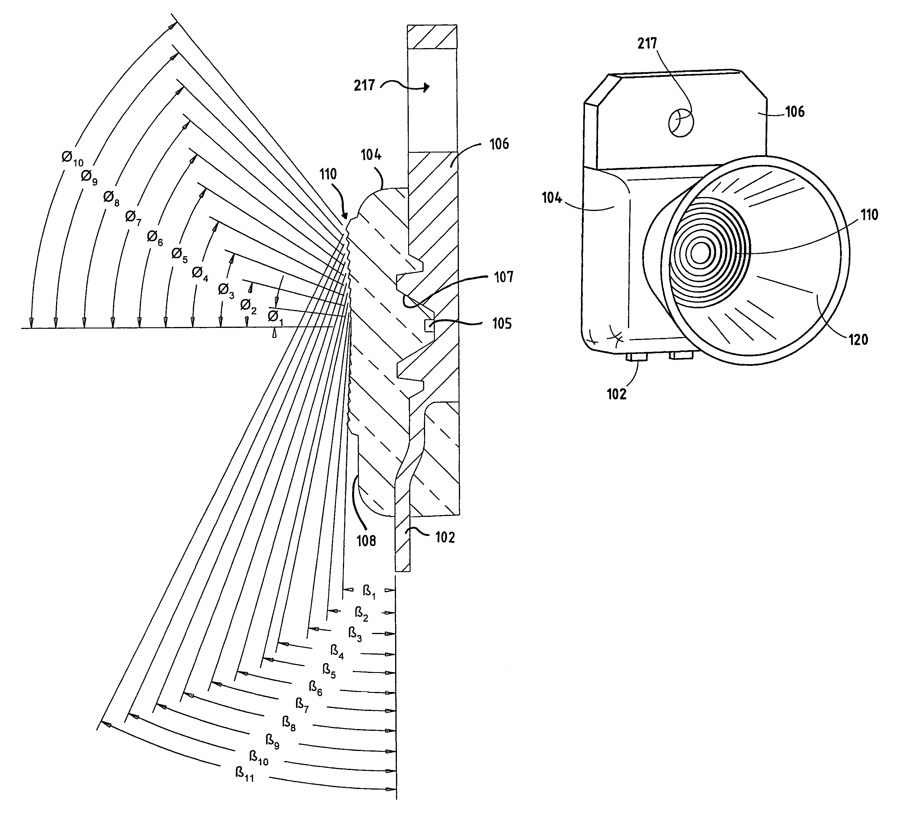
[0034]For purposes of description herein, the terms “upper,”“lower,”“right,”“left,”“rear,”“front,”“vertical,”“horizontal,”“top,”“bottom,” and derivatives thereof shall relate to the invention as viewed by a person looking directly at the radiation emitting device along the principal optical axis of the source. However, it is to be understood that the invention may assume various alternative orientations, except where expressly specified to the contrary. It is also to be understood that the specific device illustrated in the attached drawings and described in the following specification is simply an exemplary embodiment of the inventive concepts defined in the appended claims. Hence, specific dimensions, pro...
PUM
Abstract
The radiation emitter device of the present invention includes at least two radiation emitters emitting radiation of different wavelengths, first and second electrical leads electrically coupled to at least one of the radiation emitters, and an encapsulant configured to encapsulate the radiation emitters and a portion of the first and second electrical leads. The encapsulant is further configured to have a surface defining an optical lens including a plurality of concentric circular grooves. The optical lens is preferably a divergent lens. Preferably, the lens is a multi-faceted Fresnel lens structure having a plurality of risers and Fresnel facets defining the plurality of concentric circular grooves. The radiation emitter device may further include a secondary reflective cup, preferably a parabolic or elliptical reflective cup, disposed proximate the encapsulant about the periphery of the Fresnel lens structure.
Description
CROSS-REFERENCE TO RELATED APPLICATIONS[0001]This application is a continuation of U.S. patent application Ser. No. 10 / 078,906, filed on Feb. 19, 2002, now U.S. Pat. No. 6,670,207, which claims the benefit of U.S. Provisional Patent Application No. 60 / 270,054, filed on Feb. 19, 2001. Said U.S. patent application Ser. No. 10 / 078,906 is also a continuation-in-part of U.S. patent application Ser. No. 09 / 935,443, filed on Aug. 23, 2001, now U.S. Pat. No. 6,828,170 which is a divisional application of U.S. patent application Ser. No. 09 / 426,795, filed on Oct. 22, 1999, now U.S. Pat. No. 6,335,548, which claims benefit of U.S. Provisional Patent Application No. 60 / 124,493, filed on Mar. 15, 1999.[0002]This application is also a continuation-in-part of U.S. patent application Ser. No. 10 / 372,907, filed on Feb. 24, 2003, which is a continuation of U.S. patent application Ser. No. 09 / 604,056, filed on Jun. 26, 2000, now U.S. Pat. No. 6,523,976, which is a continuation of U.S. patent applicat...
Claims
Application Information
Patent Timeline
Application Date:The date an application was filed.
Publication Date:The date a patent or application was officially published.
First Publication Date:The earliest publication date of a patent with the same application number.
Issue Date:Publication date of the patent grant document.
PCT Entry Date:The Entry date of PCT National Phase.
Estimated Expiry Date:The statutory expiry date of a patent right according to the Patent Law, and it is the longest term of protection that the patent right can achieve without the termination of the patent right due to other reasons(Term extension factor has been taken into account ).
Invalid Date:Actual expiry date is based on effective date or publication date of legal transaction data of invalid patent.