Silicone pads for electronics thermal management

a technology of thermal management and silicone pads, applied in the field of thermally conductive pads, can solve the problems of increasing the probability of component malfunction, reducing the conformance of the material about the component face and the circuit board, and reducing the elasticity of the material, so as to limit the desired performance characteristics of the pad

Inactive Publication Date: 2006-10-10
LAIRD TECH INC
View PDF4 Cites 15 Cited by
  • Summary
  • Abstract
  • Description
  • Claims
  • Application Information

AI Technical Summary

Benefits of technology

[0008]Our preferred embodiment utilizes a combination of a vinyl functional fluid (“VFF”), a chain extender in the form of a hydrogen capped polysiloxane (“HCP”), a silicone polymer cross linker containing silicon-hydride groups, a powder containing thermally conductive particles (electrically insulating and / or non-insulating), and an inhibitor all mixed at room temperature and subsequently de-aired. A powder represented as electrically insulating particles, e.g., beryllium oxide, boron nitride, zinc oxide and magnesium oxide, can be used. When electrical insulation is not required metal particles, e.g., silver, aluminum and carbon, may be incorporated to enhance thermal conductivity. A platinum catalyst is added so as to accelerate cross linking. The VFF, HCP, cross linker and powder elements present the ability to vary the formulation so that the desired characteristics in the thermal pad can be achieved. Given the preferred percentages herein and recognizing the cross effect of such elements, efficient thermal pads which readily conform to the component and heat sink without the exudation of undesirable oils therefrom can be efficiently achieved.
[0010]Another important object of this invention is to provide a thermal pad, as aforesaid, which precludes the need to utilize a carrier which may limit the desired performance characteristics of the pad.

Problems solved by technology

As a result, the problem of heat dissipation generated by component operation arises which raises the probability of component malfunction, if not failure.
The silicone matrix needs to be very soft as the particle loading decreases its conformability, which in turn decreases the conformance of the material about the component face and the circuit board such that air gaps may result.
However, carriers such as Fiberglas® or substrates prevent the material from being sufficiently elastic and so have limited elongation and flexion characteristics.
Such carriers, whether Fiberglas® cloth, foam substrate, etc., are unable to intimately conform to various contours of electronic components and so leave air gaps, which cause an increase in thermal impedance.
However, the resulting material may present poor thermomechanical properties.
Moreover, when the component is compressed against the heat sink with the thermal pad therebetween, exudation of silicone oils into a monomolecular layer may result which contaminates the surrounding circuit board and components.

Method used


Image

  • Silicone pads for electronics thermal management
  • Silicone pads for electronics thermal management
  • Silicone pads for electronics thermal management

Examples


Embodiment Construction

which is a formulation suitable for use as 2.5 millimeter thick thermal pads according to exemplary embodiments.

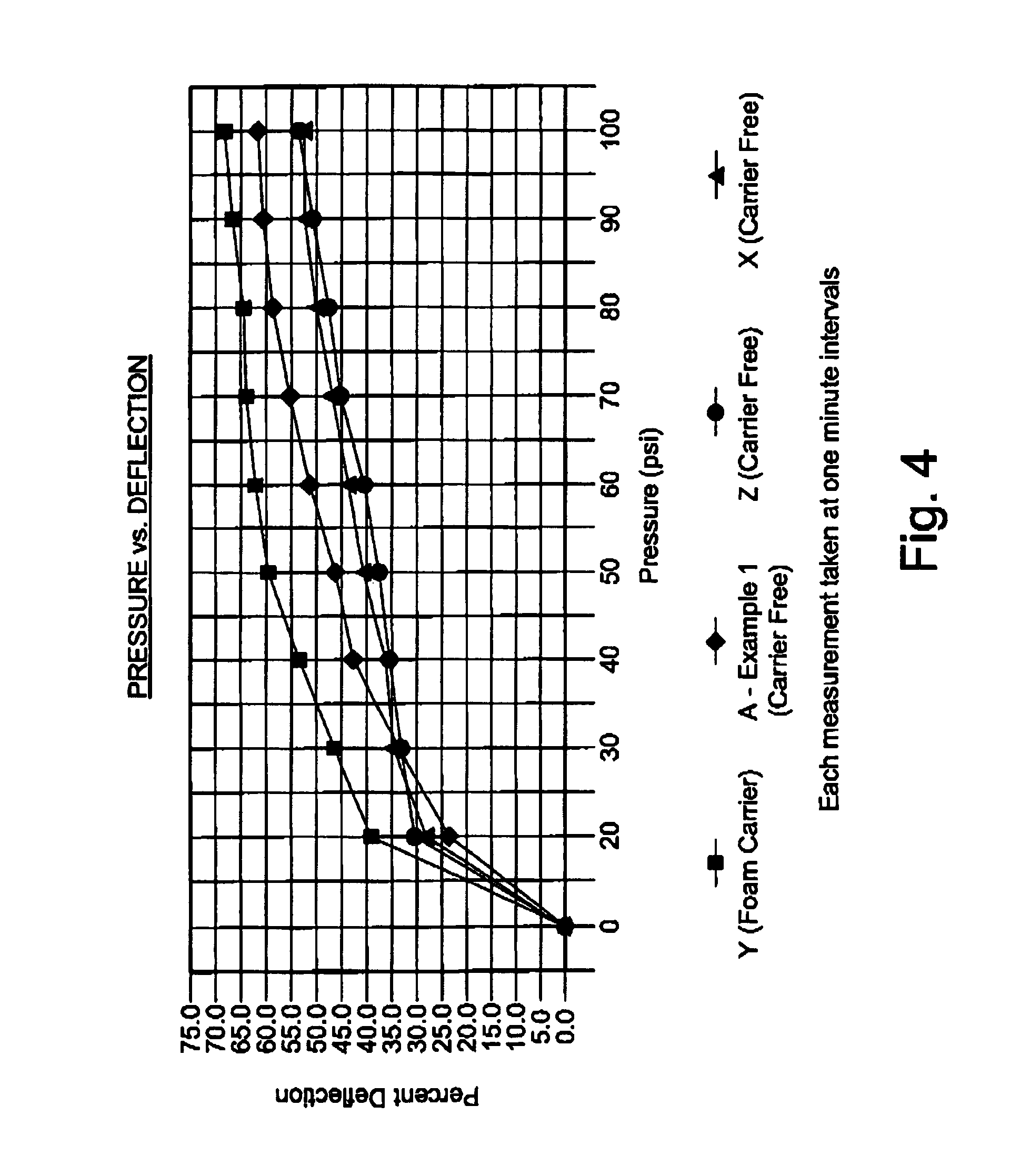
[0018]FIG. 4 is an exemplary line graph illustrating percent deflection versus pressure for each of the four product samples (also shown in FIG. 3), wherein the defection was measured as the difference in height relative to the original height taken at one minute intervals under increasing pressure.

[0019]FIG. 5 is an exemplary bar graph illustrating compression set testing results relating to the ability of each of the four product samples (also shown in FIGS. 3 and 4) to return to a starting height after compression of one hundred pounds per square inch for thirty minutes, wherein the measurements were taken ten minutes after the pressure was removed.

[0020]FIG. 6 is an exemplary bar graph illustrating thermal impedance testing results for each of the four product samples (also shown in FIGS. 3 through 5), wherein the results were taken at one hundred degrees Celsius using...


PUM

PropertyMeasurementUnit
thicknessaaaaaaaaaa
thicknessaaaaaaaaaa
thicknessaaaaaaaaaa

Abstract

A method of choosing a formulation for a carrier free pad having desired thermal conductivity and elastomeric properties therein which will produce a pad having a desirable thermal impedance. A combination of a vinyl functional fluid, hydrogen capped polysiloxane, cross linker and powder in the form of heat conductive particles with or without electrically insulating particles is utilized which is variable according to the desired thickness, elastomeric and thermal characteristics of the pad. Inhibitors and catalysts may be utilized to control reaction rate. The formulation enables one to more efficiently arrive at a final formulation for a thermal pad having the desired performance characteristics according to the job at hand.

Description

BACKGROUND OF THE INVENTION[0001]This invention relates to thermally conductive pads and, more particularly, to a method for selecting the formulation of a silicone pad providing desirable elastomeric and thermally conductive characteristics therein.[0002]Circuit designs for electronic devices have become more sophisticated resulting in various components closely packed on circuit boards. As a result, the problem of heat dissipation generated by component operation arises which raises the probability of component malfunction, if not failure.[0003]Heat dissipation may be achieved by the use of a heat sink, whether in the form of a separate plate or device chassis, which is positioned adjacent the component for a heat transfer thereto. The interface between the respective faces may be irregular resulting in air spaces therebetween. As air is a poor heat conductor the spaces denigrate the heat transfer between the component and the heat sink. Thus, the operating temperature of the comp...

Claims


Application Information

Patent Timeline
Patent Type & Authority Patents(United States)
IPC IPC(8): C08L83/00
CPCC08L83/04C08G77/12C08G77/20
Inventor JARNJEVIC, SNJEZANAEATON, MANFORD L.
Owner LAIRD TECH INC
Why Eureka
Try Eureka