Display panel device
a display panel and display screen technology, applied in the direction of identification means, instruments, gas-filled discharge tubes, etc., can solve the problems of affecting the display effect, the filter plate is not desired for a large screen of the plasma display panel, and the distortion of the reflected image of the external light, so as to achieve the effect of little display distortion
- Summary
- Abstract
- Description
- Claims
- Application Information
AI Technical Summary
Benefits of technology
Problems solved by technology
Method used
Image
Examples
example 1
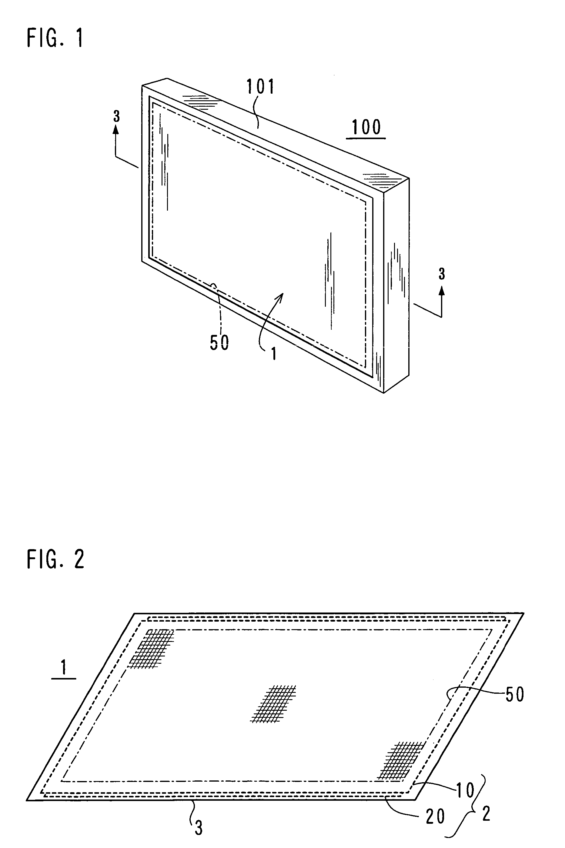
[0029]FIG. 1 shows an appearance of a display device according to the present invention. A display device 100 is a flat type display having a 32-inch diagonal screen 50. A dimension of the screen 50 is 0.72 meters in the horizontal direction and 0.40 meters in the vertical direction. A facing cover 101 that defines a plane size of the display device 100 has an opening that is larger than the screen 50, so that a front face of a display panel device 1 is exposed in part.
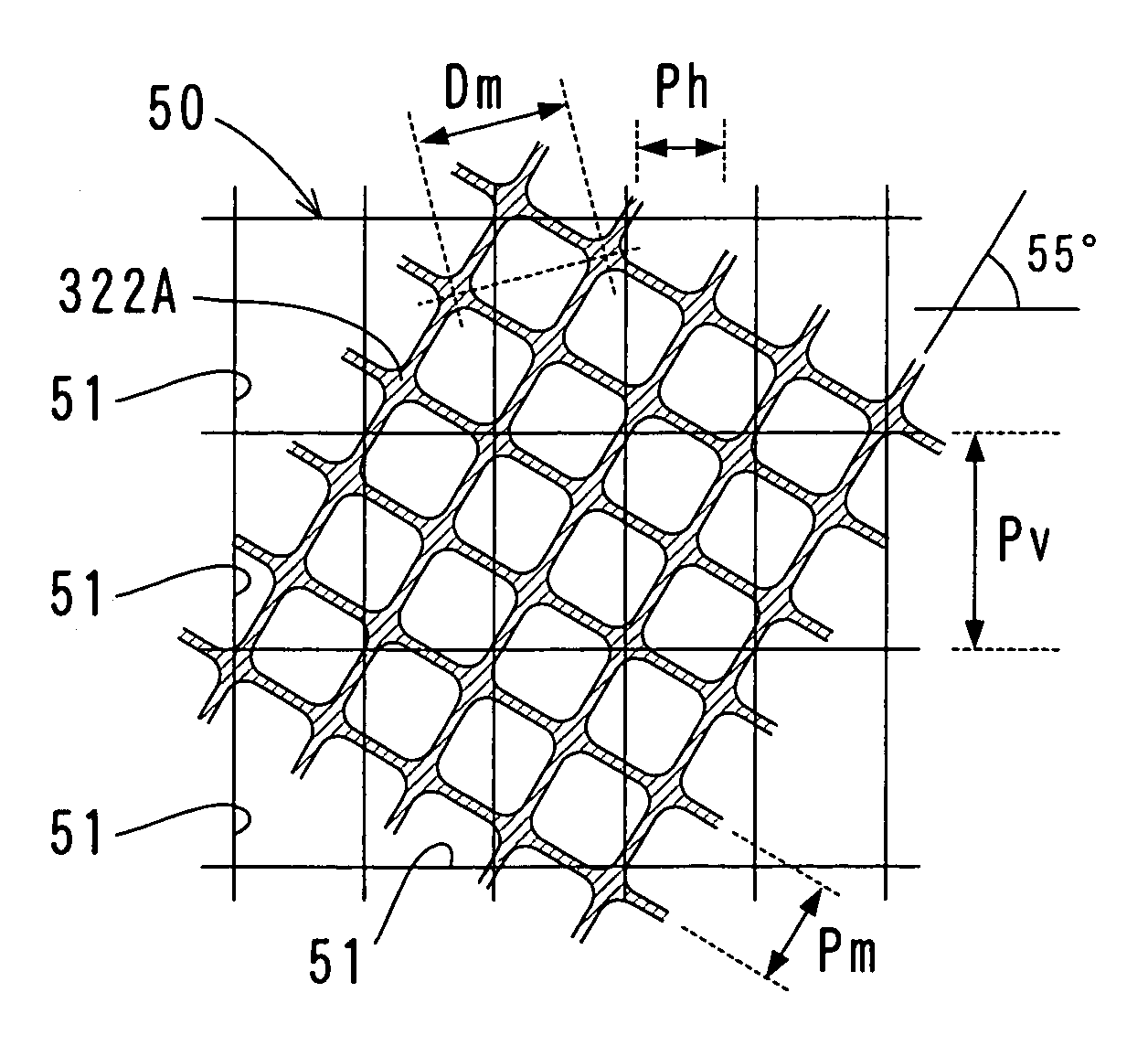
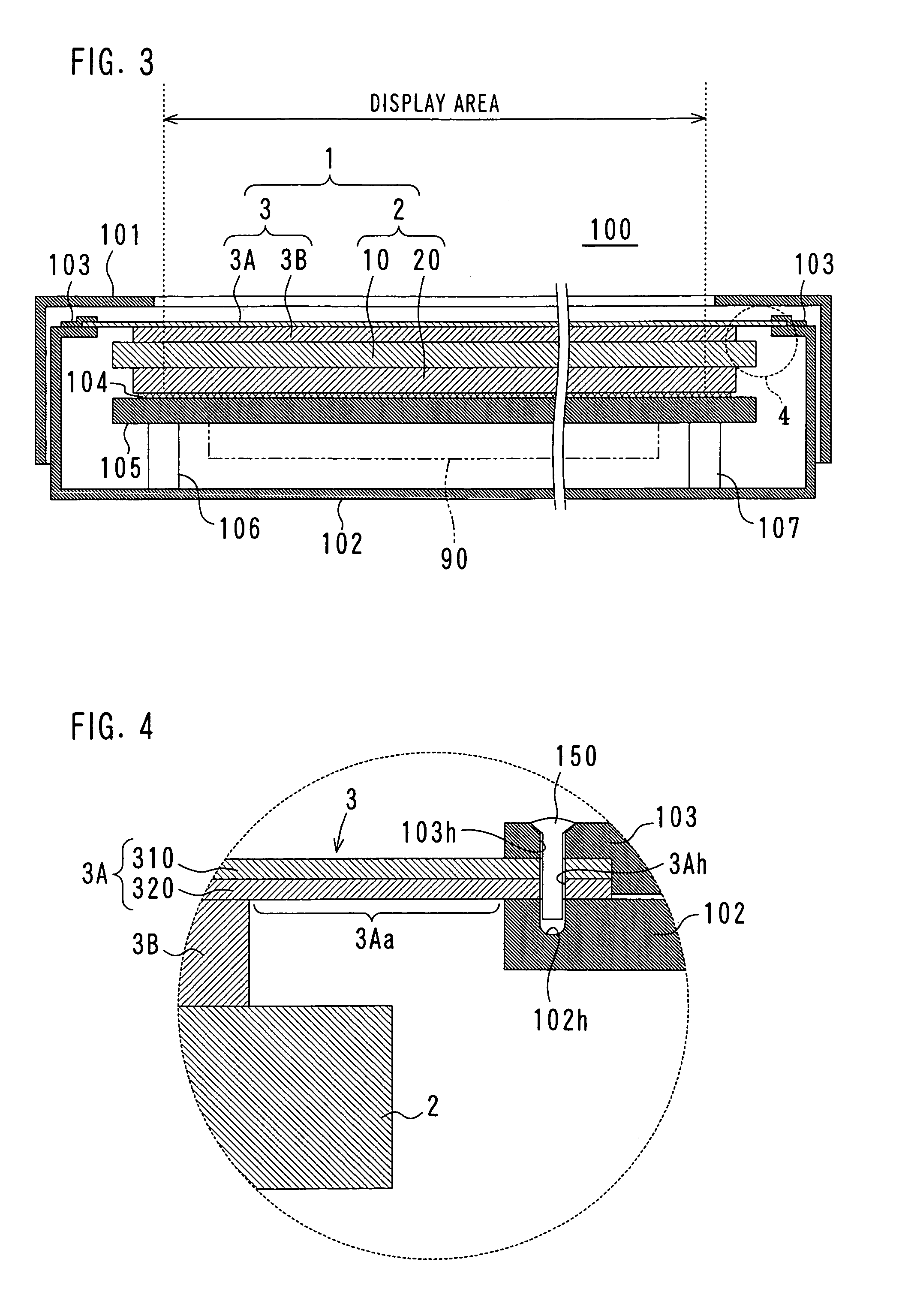
[0030]FIG. 2 shows a structure of the display panel device. The display panel device 1 includes a plasma display panel 2 that is a device that constitutes a screen and a front sheet 3 as a filter member that is glued directly on the front face of the plasma display panel 2 to be a display face. The plasma display panel 2 is a self-luminous type device that emits light by gas discharge, which includes a front face plate 10 and a rear face plate 20. Each of the front face plate 10 and the rear face plate 20 is a structu...
example 2
[0049]FIG. 10 shows a second example of a structure of the display device. A basic structure of the display device 200 is the same as the above-mentioned display device 100. In FIG. 10 and in the following drawings, structural elements denoted by the same reference numerals as in FIG. 3 are the same structural elements as the display device 100.
[0050]The display device 200 has a display panel device 5 that is a screen module. The display panel device 5 includes a plasma display panel 2 and a front sheet 6, and the front sheet 6 includes a front portion 6A and a rear portion 6B. A layer structure of the front sheet 6 is-the same as in FIG. 6. In the display device 200, a plane size of the front portion 6A is larger than the above-mentioned example, and four sides of the front portion 6A are bent backward substantially in perpendicular manner, so that the end portions of the front portion 6A are fixed to a conductive housing 202. The fixing method is sandwiching the front portion 6A b...
example 3
[0054]FIG. 12 shows a third example of a structure of the display device. A structure of the display device 300 is substantially the same as the above-mentioned display device 200. The display device 300 is characterized in that the inner rim of the front face of the facing cover 301 is close to a screen area, and sound absorbing members 351 and 352 are arranged between the facing cover 301 and the front sheet 6. The sound absorbing members 351 and 352 are glued on the facing cover 301 in advance, and the display panel device 5 is covered with the facing cover 301 so that the sound absorbing members 351 and 352 are pressed onto the front sheet 6. As the sound absorbing members 351 and 352 are flexible sponge, no excessive force is applied to the plasma display panel 2. As audible sound noises due to vibration of the plasma display panel 2 (called an abnormal sound) increases at a peripheral portion of the plasma display panel 2, the noises can be reduced substantially by arranging t...
PUM
 Abstract
Description
Claims
Application Information
 - R&D
- Intellectual Property
- Life Sciences
- Materials
- Tech Scout
- Unparalleled Data Quality
- Higher Quality Content
- 60% Fewer Hallucinations
Browse by: Latest US Patents, China's latest patents, Technical Efficacy Thesaurus, Application Domain, Technology Topic, Popular Technical Reports.
© 2025 PatSnap. All rights reserved.Legal|Privacy policy|Modern Slavery Act Transparency Statement|Sitemap|About US| Contact US: help@patsnap.com


