Supercharge Your Innovation With Domain-Expert AI Agents!

Ventilated reflector

a technology of reflectors and reflector bodies, applied in incadescent envelopes/vessels, lighting and heating equipment, instruments, etc., can solve the problems of efficiency losses of the reflector assembly, and achieve the effect of reducing the thickness of the reflector body, reducing the efficiency loss of the reflector assembly, and reducing the thickness of the wall

Inactive Publication Date: 2006-10-10
THE BOEING CO
View PDF11 Cites 7 Cited by
  • Summary
  • Abstract
  • Description
  • Claims
  • Application Information

AI Technical Summary

Benefits of technology

[0007]According to yet another aspect of the invention, a method to construct a reflector assembly comprises: forming an inner cavity of a reflector body about concentric geometric curves; reducing a reflector body wall thickness in an area local to a light discharge end of the reflector body; creating a plurality of apertures through the reflector body outside of the area having reduced wall thickness; aligning a coolant source with the apertures; and positioning an arc lamp within the reflector body away from a direct impingement path between a coolant entering the apertures and the arc lamp.
[0008]Advantages of a reflector assembly of the present invention include provision of a reflector body formed about concentric geometric curves, and the definition of a wall thickness change in an area between the geometric curves. Providing apertures at or adjacent to the change in reflector body wall thickness allows a positive flow of cooling medium into the reflector body, while allowing an arc lamp location outside of a direct impingement path of the cooling medium. Also, by locating the apertures at the change in reflector body wall thickness, light rays from the arc lamp cannot directly enter the apertures, and thereby lead to efficiency losses of the reflector assembly. A longer arc lamp life can result from the cooling paths created by the apertures of the present invention.

Problems solved by technology

Also, by locating the apertures at the change in reflector body wall thickness, light rays from the arc lamp cannot directly enter the apertures, and thereby lead to efficiency losses of the reflector assembly.

Method used


Image

  • Ventilated reflector
  • Ventilated reflector
  • Ventilated reflector

Examples


Embodiment Construction

[0018]The following description of the preferred embodiments is merely exemplary in nature and is in no way intended to limit the invention, its application, or uses.

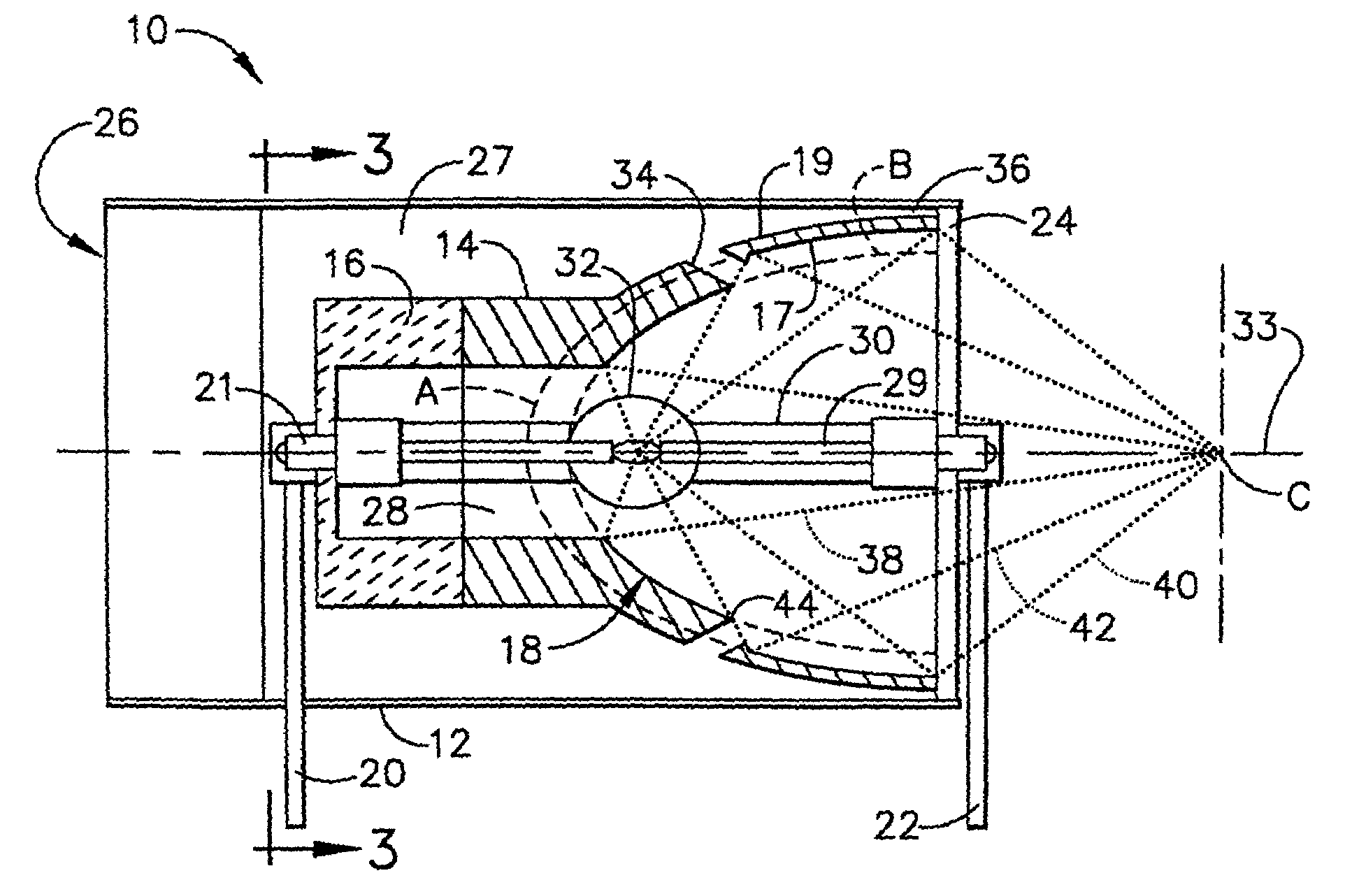
[0019]According to a preferred embodiment of the present invention, and referring to FIG. 1, a reflector assembly 10 includes a plenum 12, a reflector body 14, and a non-conductive mount 16. Non-conductive mount 16 is directly joined to reflector body 14 forming a closed end of reflector body 14. Non-conductive mount 16 is generally formed of a non-electrically conductive material including ceramic materials. Plenum 12 surrounds the combination of reflector body 14 and non-conductive mount 16. Plenum 12 is preferably formed of a metallic material, including aluminum or steel. Other materials including polymeric materials or composite materials can also be used to form plenum 12. Reflector body 14 is preferably formed of a metallic material including aluminum having polished and / or coated inner surfaces as generally know...


PUM


Abstract

A reflector assembly includes at least one reflector body having an inner cavity including a first inner surface conformable along a first geometric curve, and a second inner surface conformable along a second geometric curve. An outer surface is conformable about the first geometric curve. A plurality of through apertures are spaced about the reflector body, each formed between the outer surface and a transition region between the first inner surface and the second inner surface. A coolant flow source directs a coolant toward the reflector body. A first portion of the coolant contacts the outer surface, and a second portion of the coolant enters the inner cavity through the apertures. Providing apertures at or adjacent to the change in reflector body wall thickness allows a positive flow of cooling medium around and into the reflector body, while positioning an arc lamp outside of a cooling medium direct impingement path.

Description

FIELD OF THE INVENTION[0001]The present invention relates to a reflector assembly used to focus or direct light and more specifically to a device and method for reflecting light while providing for reflector cooling of a reflector assembly.BACKGROUND OF THE INVENTION[0002]Illuminators are used in many applications including for fiber optic illumination, commercial illumination including street lamps etc., and in public consumption such as illumination for stadiums. Illuminators locate the source of light remote from the area to be illuminated. Illuminators generally provide a reflector body which contains an arc lamp. The light generated from the arc lamp is reflected from the internal geometry of the reflector body to the general area where light is required.[0003]One of the problems with arc lamp illuminators is the control of the source heat load. Passive methods for controlling the thermal heat load include radiative fins installed on the outer body of the reflector body. Active...

Claims


Application Information

Patent Timeline
Patent Type & Authority Patents(United States)
IPC IPC(8): H01J5/16H01J61/40H01K1/26H01K1/30F21V7/00F21V7/08F21V7/09F21V29/02F21V29/505H01J61/86
CPCF21V7/0025F21V7/08F21V7/09H01J61/86F21V29/505F21V29/02F21V2200/17F21V29/56G03B21/2026
Inventor GUY, JAMES K
Owner THE BOEING CO
Features
  • R&D
  • Intellectual Property
  • Life Sciences
  • Materials
  • Tech Scout
  • Unparalleled Data Quality
  • Higher Quality Content
  • 60% Fewer Hallucinations
Learn More